Review
. 2011 Mar;1810(3):239-50.
doi: 10.1016/j.bbagen.2010.07.002. Epub 2010 Jul 23.

Engineering systems for the generation of patterned co-cultures for controlling cell-cell interactions

Affiliations
Review

Engineering systems for the generation of patterned co-cultures for controlling cell-cell interactions

Hirokazu Kaji et al. Biochim Biophys Acta. 2011 Mar.

Abstract

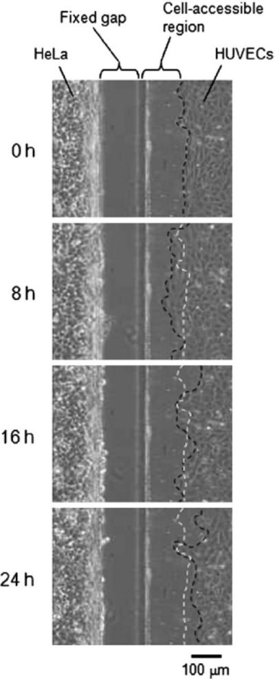
Background: Inside the body, cells lie in direct contact or in close proximity to other cell types in a tightly controlled architecture that often regulates the resulting tissue function. Therefore, tissue engineering constructs that aim to reproduce the architecture and the geometry of tissues will benefit from methods of controlling cell-cell interactions with microscale resolution.

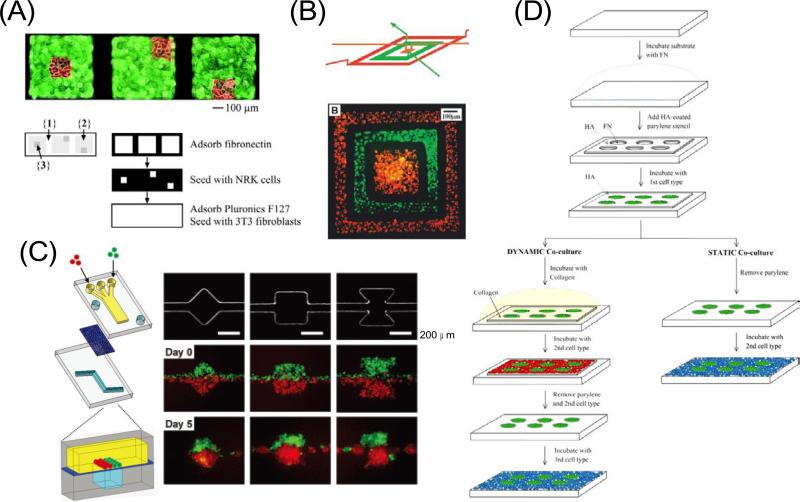
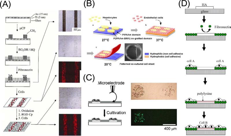
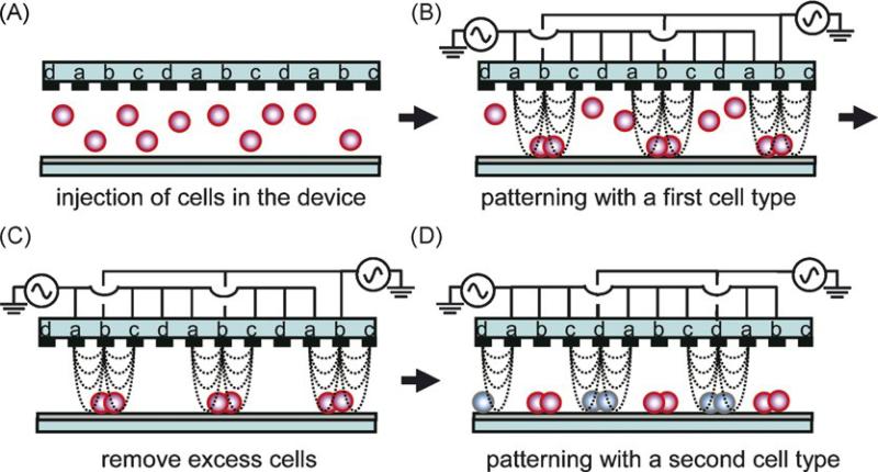
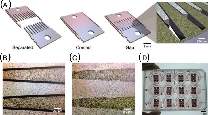
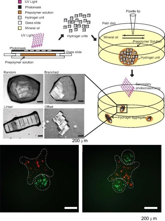
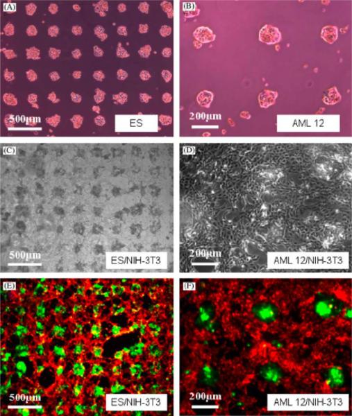
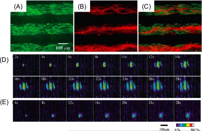
Scope of the review: We discuss the use of microfabrication technologies for generating patterned co-cultures. In addition, we categorize patterned co-culture systems by cell type and discuss the implications of regulating cell-cell interactions in the resulting biological function of the tissues.

Major conclusions: Patterned co-cultures are a useful tool for fabricating tissue engineered constructs and for studying cell-cell interactions in vitro, because they can be used to control the degree of homotypic and heterotypic cell-cell contact. In addition, this approach can be manipulated to elucidate important factors involved in cell-matrix interactions.

General significance: Patterned co-culture strategies hold significant potential to develop biomimetic structures for tissue engineering. It is expected that they would create opportunities to develop artificial tissues in the future. This article is part of a Special Issue entitled Nanotechnologies - Emerging Applications in Biomedicine.


Figures

Figure 1
Figure 1
Patterned co-cultures based on soft lithographic methods. (A) Patterning two different cell types using a multilevel PDMS stamp. The stamp was placed against a Petri dish masking region 1. Regions 2 and 3 were then coated with fibronectin. When the stamp was pushed against the substrate, the middle level collapsed, shielding region 2. After NRK cells (red) were seeded onto region 3, the stamp was removed, the substrate was immersed in pluronics F127 to render region 1 non-cell-adhesive, and fibroblasts (green) were seeded onto region 2 [22]. Copyright (2002) National Academy of Sciences, U.S.A. (B) Two cell types deposited on a tissue culture dish in a concentric square pattern by using a 3D microfluidic system. These cells were cultured in the channel for 24 hours to grow and spread into a confluent layer and the fluorescence micrograph was taken after the PDMS channel was removed [25]. Copyright (2000) National Academy of Sciences, U.S.A. (C) Compartmentalized microfluidic system for co-culturing spheroids. Two PDMS channel layers were separated by a semi-porous polycarbonate membrane which is rendered resistant to cell adhesion. The top channel was a straight channel with a dead-end. The bottom channel consisted of a straight channel with or without chambers. Cells were introduced into the top channel using multiple laminar flows. Micrographs show the bottom layer geometry and actual cellular patterning. MDA-MB-231 cells (green) and COS7 cells (red), were juxtaposed in the top layer as fluid focuses them together into one channel in the bottom layer. Each type of cell self-aggregated to form multiple spheroids [26]. Reproduced by permission of The Royal Society of Chemistry. (D) Static and dynamic patterned co-cultures using microfabricated parylene-C stencils [30]. Reproduced by permission of The Royal Society of Chemistry.
Figure 2
Figure 2
Patterned co-cultures based on switchable surfaces. (A) An electroactive substrate to pattern two cell populations into a co-culture. Microcontact printing was used to pattern hexadecanethiolate onto a gold substrate. A second monolayer was assembled on the remaining regions of gold by immersing the substrate into a solution of hydroquinone-terminated alkanethiol (HQ) and penta(ethylene glycol)-terminated alkanethiol (EG5OH). The substrate was then immersed in a solution of fibronectin, followed by fibronectin adsorption only to the methyl-terminated regions of the monolayer. Fibroblasts attached only to the regions presenting fibronectin, and when cultured in serum-containing media, divided to fill these regions entirely. The surrounding inert monolayer strictly confined the cell to the rectangular regions. Electrochemical oxidation of the monolayer in the presence of media containing RGD-Cp led to the immobilization of the peptide. Micrographs show that the two cell populations are patterned on the substrate [42]. Copyright (2001) National Academy of Sciences, U.S.A. (B) Patterning co-culture and harvesting of co-cultured cell sheet using thermally responsive surfaces. First cell type was seeded and cultured at 27°C, resulting in localization of the cells onto P(IPAAm–BMA) co-grafted islands showing hydrophobic nature. Second cell type seeded and cultured at 37 °C, resulted in generation of patterned co-cultures. Decreasing temperature to 20 °C induced detachment of co-cultured cell sheet [44]. Reprinted from Biochem. Biophys. Res. Commun, 348, Y. Tsuda, A. Kikuchi, M. Yamato, G. Chen, T. Okano, Heterotypic cell interactions on a dually patterned surface, 937–944, Copyright (2006), with permission from Elsevier. (C) Overwriting cell population on a previously cell-patterned substrate using oxidation by a microelectrode. Optical and fluorescence micrographs of a couple of HeLa cell populations patterned in a stepwise fashion. The population on the left side was first cultured and stained with calcein-AM, followed by the local oxidation treatment to make the population on the right side [53]. Reprinted with permission from H. Kaji, M. Kanada, D. Oyamatsu, T. Matsue, M. Nishizawa, Microelectrochemical approach to induce local cell adhesion and growth on substrates, Langmuir, 20 (2004) 16–19. Copyright 2004 American Chemical Society. (D) Layer-by-layer deposition of ionic biomolecules to generate patterned co-cultures. Reprinted from Biomaterials, 59, A. Khademhosseini, K. Y. Suh, J. M. Yang, G. Eng, J. Yeh, S. Levenberg, R. Langer, Layer-by-layer deposition of hyaluronic acid and poly-l-lysine for patterned cell co-cultures, 3583–3592, Copyright (2004), with permission from Elsevier.
Figure 3
Figure 3
Pattering two different cell types based on a dielectrophoretic method. An interdigitated array (IDA) electrode with four independent microelectrode subunits was used as a template to form cellular micropatterns (A). The n-DEP force was induced by applying an AC voltage to direct cells toward a weaker region of electric field strength (B). After removing excess cells from the device (C), a second cell type was introduced into the device and, by changing the AC voltage mode, these cells were guided to other areas to form a different pattern (D) [63]. Reprinted from Biosens. Bioelectron., 24, M. Suzuki, T. Yasukawa, H. Shiku, T. Matsue, Negative dielectrophoretic patterning with different cell types, 1043–1047, Copyright (2008), with permission from Elsevier.
Figure 4
Figure 4
Patterned co-cultures based on a mechanically configurable device. (A) Microfabricated silicon parts can be fully separated (left), locked together with comb fingers in contact (center), or slightly separated (right). (B, C) Micrographs of hepatocytes (darker cells) and 3T3 fibroblasts cultured on the comb fingers. (D) Devices in a standard 12-well plate [64]. Copyright (2007) National Academy of Sciences, U.S.A.
Figure 5
Figure 5
3D patterned co-cultures based on directed assembly of cell-laden hydrogels. Cell-laden rectangular hydrogels were created directly by photopolymerization using UV through a photomask, then allowed to aggregate and self-assemble in a hydrophobic media. Fluorescence images show microgel assembly composed of cross-shaped gels containing red-staining cells and rod-shaped gels containing green-stained cells [72]. Copyright (2008) National Academy of Sciences, U.S.A.
Figure 6
Figure 6
Patterned mono and co-cultures on HA/collagen surfaces. Adhesion of (A) ES cells, (B) mouse hepatocytes on FN coated areas on HA-patterned surface after 8 h incubation period. (C) ES aggregates formed by mouse fibroblasts on collagen treated HA-patterned surface (containing previously attached hepatocytes) after 3 day incubation. (D) Co-cultivated hepatocytes and fibroblasts. (E) Fluorescent images for co-culture of ES cells/fibroblasts and (F) co-culture of hepatocytes/fibroblasts at day 3 [56]. Reprinted from Biomaterials, 27, J. Fukuda, A. Khademhosseini, J. Yeh, G. Eng, J. Cheng, O.C. Farokhzad, R. Langer, Micropatterned cell co-cultures using layer-by-layer deposition of extracellular matrix components, 1479–1486, Copyright (2006), with permission from Elsevier.
Figure 7
Figure 7
Fluorescence images for astrocyte-neuron co-cultures. (A) FITC image for selectively labeled the astrocytes, (B) Rhodamine image for selectively labeled the neurons, (C) Overlapping images of (A) and (B). (D) Astrocytes loaded with fluorescent calcium indicator after mechanical stimulation. (E) Astrocytes loaded with both calcium indicator and purinergic receptor antagonist in the extracellular saline [84]. Reprinted with permission from H. Takano, J.-Y. Sul, M.L. Mazzanti, R.T. Doyle, P.G. Haydon, M.D. Porter, Micropatterned substrates: Approach to probing intercellular communication pathways, Anal. Chem., 74 (2002) 4640–4646. Copyright 2002 American Chemical Society.
Figure 8
Figure 8
Phase-contrast pictures for co-cultivated HeLa cells and HUVECs that were separated by 100 um gap-type barrier. White-dotted lines represent initial HUVEC border while black-dotted lines follow the borders of moving HUVECs [65]. Reproduced by permission of The Royal Society of Chemistry.
Figure 9
Figure 9
Cellular communication between cells. (A) Inlet channels in the hydrogel. (B) Layout of BAC and LADMAC cells in hydrogels. (C) Propidium iodide stained BAC cells (2 day culture) without CSF-1 source [69]. Reprinted from Biomaterials, 29, A.P. Wong, R. Perez-Castillejos, J.C. Love, G.M. Whitesides, Partitioning microfluidic channels with hydrogel to construct tunable 3-D cellular microenvironments, 1853–1861, Copyright (2008), with permission from Elsevier.

Similar articles

Cited by

References

    1. Khademhosseini A, Langer R, Borenstein J, Vacanti JP. Microscale technologies for tissue engineering and biology. Proc. Natl. Acad. Sci. USA. 2006;103:2480–2487. - PMC - PubMed
    1. Liu WF, Chen CS. Cellular and multicellular form and function. Adv. Drug Deliv. Rev. 2007;59:1319–1328. - PMC - PubMed
    1. Khetani SR, Bhatia SN. Engineering tissues for in vitro applications. Curr. Opin. Biotechnol. 2006;17:524–531. - PubMed
    1. Bhatia SN, Balis UJ, Yarmush ML, Toner M. Effect of cell-cell interactions in preservation of cellular phenotype: cocultivation of hepatocytes and nonparenchymal cells. FASEB J. 1999;13:1883–1900. - PubMed
    1. Guguenguillouzo C, Clement B, Baffet G, Beaumont C, Morelchany E, Glaise D, Guillouzo A. Maintenance and reversibility of active albumin secretion by adult-rat hepatocytes co-cultured with another liver epithelial-cell type. Exp. Cell Res. 1983;143:47–54. - PubMed

Publication types

Substances