Review
. 2011 Jan;7(1):31-56.
doi: 10.1016/j.actbio.2010.07.028. Epub 2010 Jul 24.

Liquid-liquid two-phase systems for the production of porous hydrogels and hydrogel microspheres for biomedical applications: A tutorial review

Affiliations
Review

Liquid-liquid two-phase systems for the production of porous hydrogels and hydrogel microspheres for biomedical applications: A tutorial review

Donald L Elbert. Acta Biomater. 2011 Jan.

Abstract

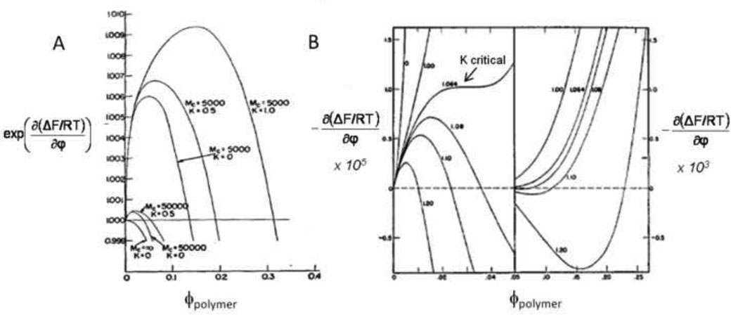
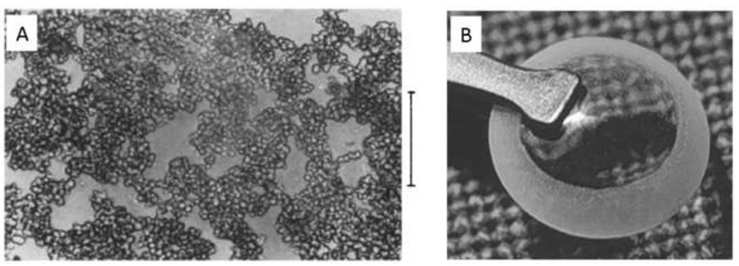
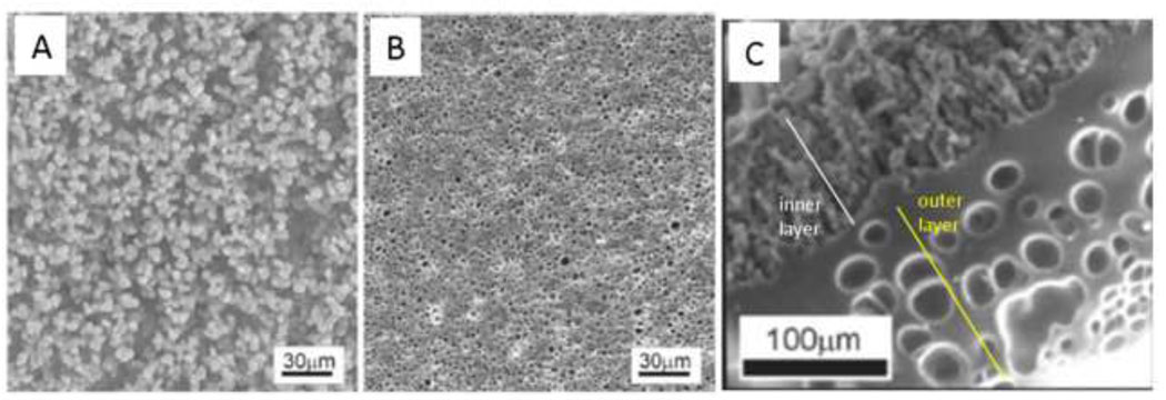
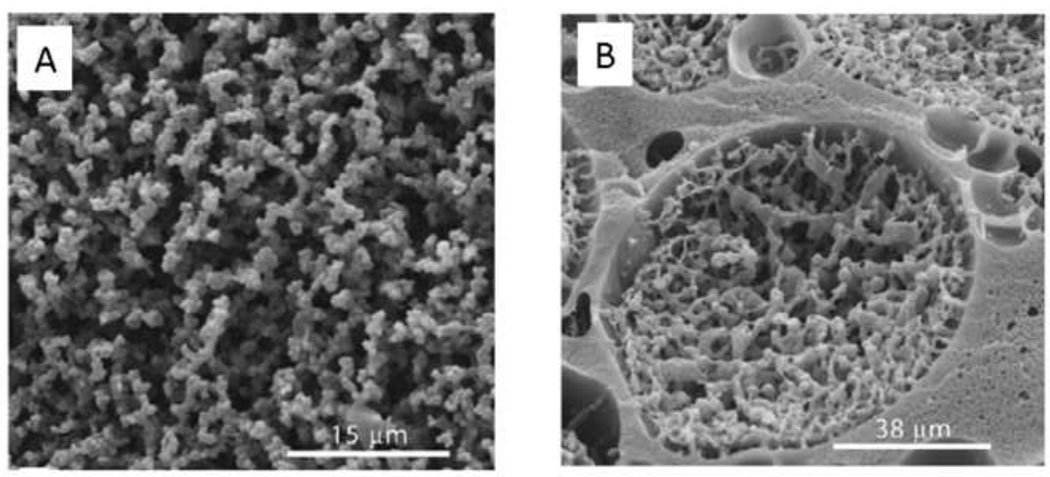
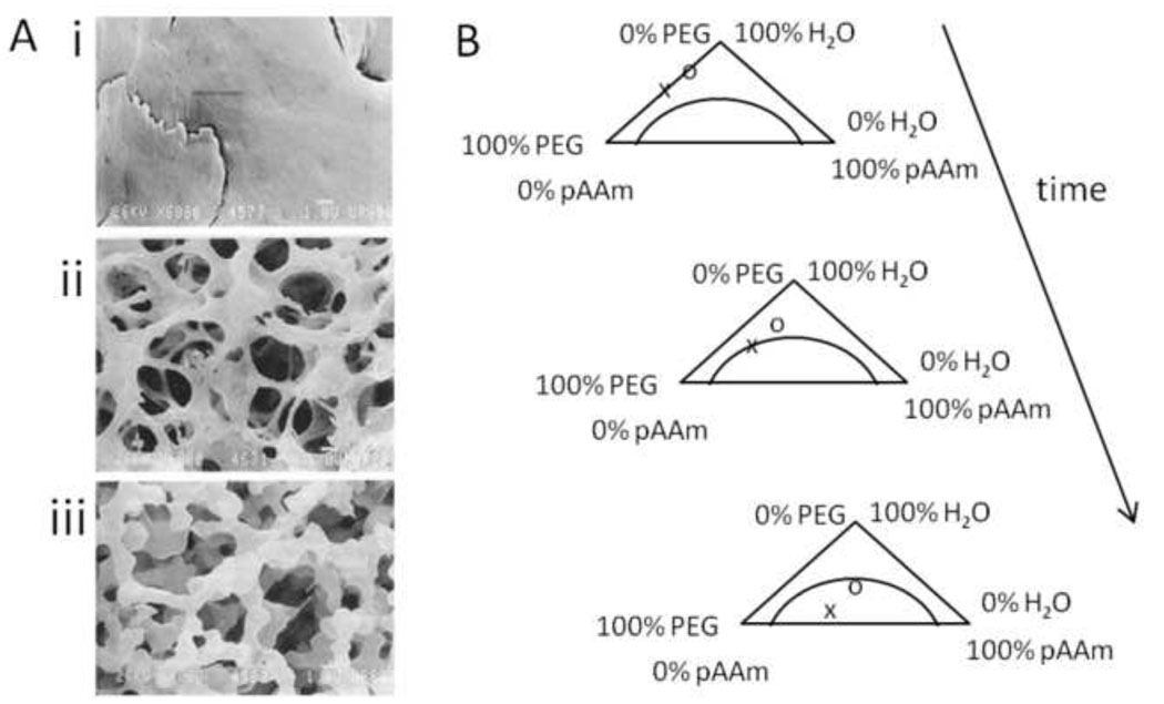
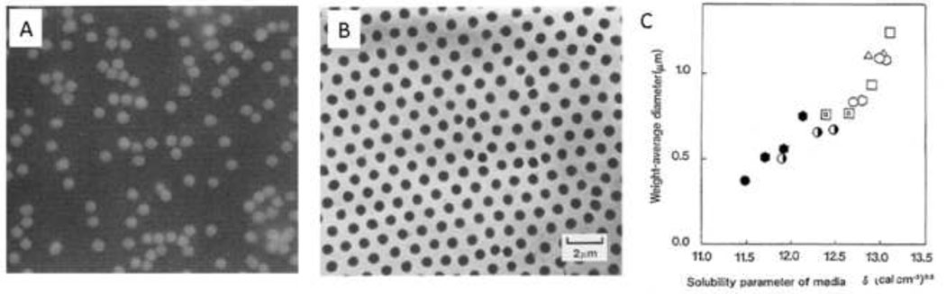
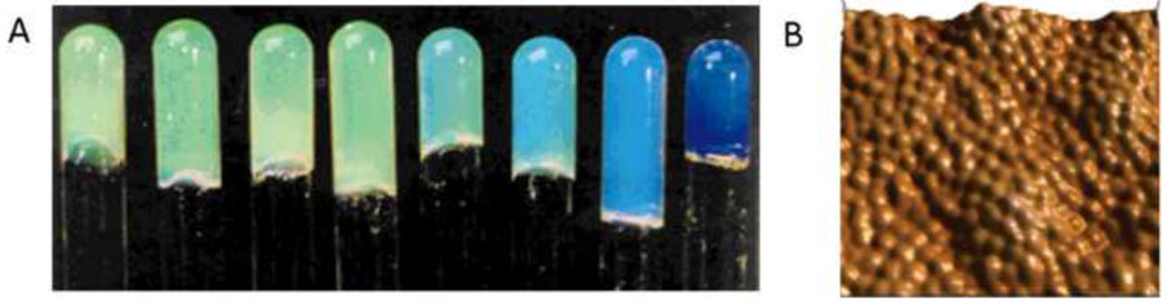
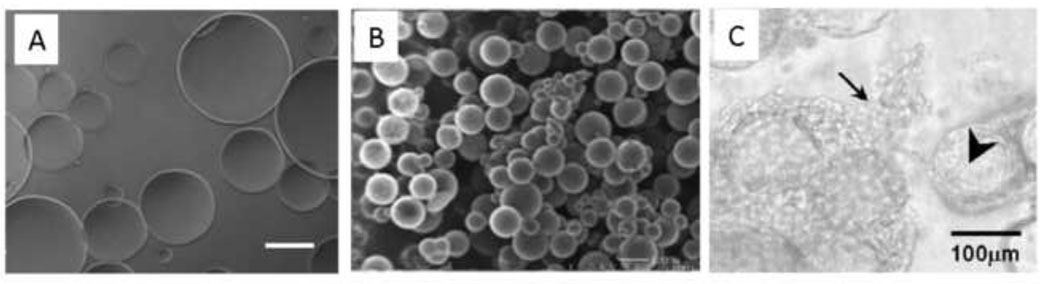
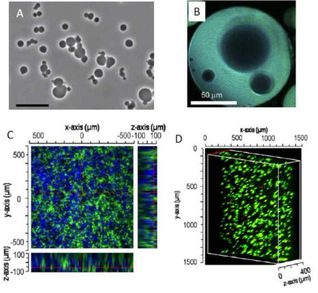
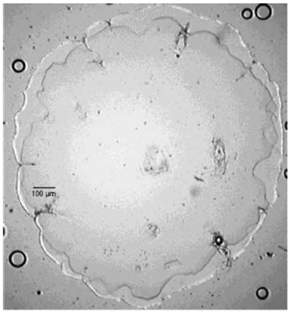
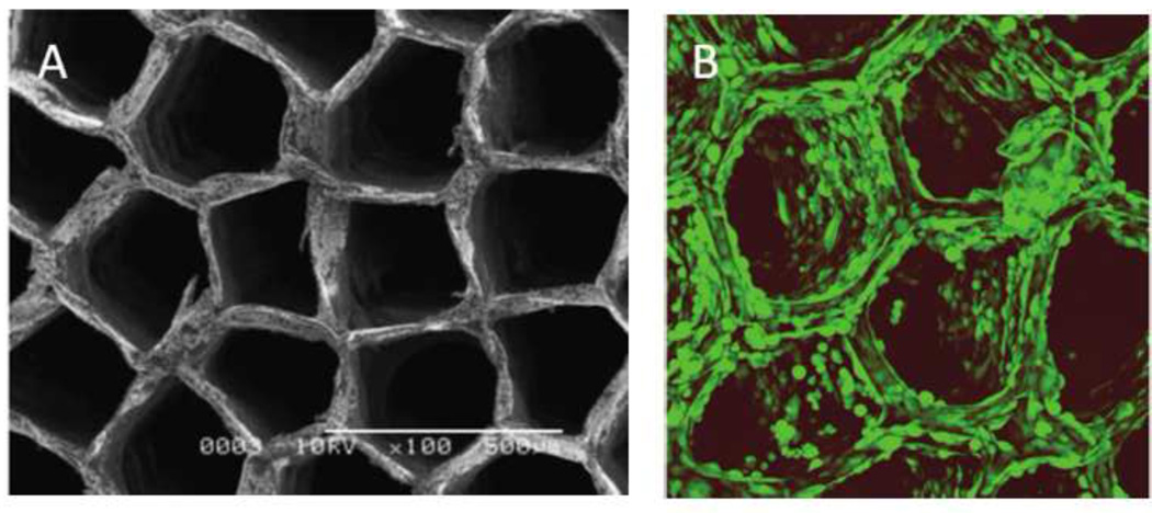
Macroporous hydrogels may have direct applications in regenerative medicine as scaffolds to support tissue formation. Hydrogel microspheres may be used as drug-delivery vehicles or as building blocks to assemble modular scaffolds. A variety of techniques exist to produce macroporous hydrogels and hydrogel microspheres. A subset of these relies on liquid-liquid two-phase systems. Within this subset, vastly different types of polymerization processes are found. In this review, the history, terminology and classification of liquid-liquid two-phase polymerization and crosslinking are described. Instructive examples of hydrogel microsphere and macroporous scaffold formation by precipitation/dispersion, emulsion and suspension polymerizations are used to illustrate the nature of these processes. The role of the kinetics of phase separation in determining the morphology of scaffolds and microspheres is also delineated. Brief descriptions of miniemulsion, microemulsion polymerization and ionotropic gelation are also included.


Figures

Figure 1
Figure 1. Thermodynamics of phase separation
(A) The Flory-Huggins equation (Equation [1]) describes the free energy of mixing as a function of composition (ϕ). The free energy of mixing is shown for a mixture of two polymers (degrees of polymerization of 150 and 100) and different values of the Flory interaction parameter (χ). Binodal points are shown as open circles and spinodal points are shown as x’s. The dependence of the Flory interaction parameter on temperature determines if a lower or upper critical solution temperature exists. The critical point occurs at χ = 0.0165. (B) Phase diagram of PEG in water. The degree of polymerization of PEG is listed next to each binodal line. A one phase solution exists below the binodal lines, with the minima of the lines at the critical temperature (lower critical solution temperature, LCST). For low molecular weight PEG, closed loop behavior is observed, with an upper critical solution temperature (UCST) above the LCST. Adapted from Matsuyama & Tanaka, Physical Review Letters, 65, 341–344, 1990. (C) Salts greatly affect the LCST of PEG in water. Kosmotropic (water-structuring) salts are most effective at reducing the LCST. From Bailey & Callard, J. Appl. Polym. Sci., 1, 56–62, 1959. (D) Pressure also affects the phase behavior. Phase separation occurs at room temperature for PEG mol. wt. 21,000 (circles), PEG mol. wt. 1360 (squares) and PVP (dotted line) in water at elevated pressures. Adapted with permission from Sun & King, Macromolecules, 31, 6383–6386, Copyright 1998 American Chemical Society.
Figure 2
Figure 2. Hypothetical phase diagrams for a polymer exhibiting LCST phase behavior
(A) In a thermally induced phase separation, the solution is initially a single phase (i). The temperature is raised until the two phase region is entered (ii). The binodal line is solid and the spinodal line is dashed. If the solution is ‘quenched’ deeply so as to cross the spinodal line, phase separation is by spinodal decomposition. (B) In a precipitation polymerization, the temperature remains constant. The monomer is soluble throughout the polymerization (i). The polymer that forms has a different phase diagram from the monomer (ii). Polymer chains with different degrees of polymerization have distinct phase diagrams, as evident from the Flory-Huggins equation (Equation [1]). At the polymerization temperature, polymer chains above a certain degree of polymerization and concentration may phase separate. As shown in (ii), phase separation would be by nucleation and growth because only the binodal line is surpassed, while phase separation by spinodal decomposition will occur in (i).
Figure 3
Figure 3. ‘Pinning’ of phase separation during spinodal decomposition
(A) The inverse of the wave vector with peak intensity, qm, reveals the characteristic dimension of the phase separated domains. This is measured over time following a deep quench beyond the spinodal point of a poly(butadiene)/poly(isoprene) blend. The log-log plot reveals the power law nature of the process. Initially, the slope of one indicates a linear relationship between the characteristic size of the phase separated domain and time. Eventually, the power law exponent changes and growth appears to halt (i.e. ‘pinned’). In fact, the growth law has simply changed, with an exponent at longer times of 1/3. The change in growth law occurs at the percolation-to-cluster transition. Reprinted with permission from Crist, B., Macromolecules, 29, 7276–7279, Copyright 1996 American Chemical Society. (B) The same phenomenon can be observed with PEG in PBS + 0.6 M sodium sulfate. When the temperature is raised to 37°C, dynamic light scattering showed a linear growth in the mean diameter, followed by pinning. This occurred with PEG alone at 1% or 2% (w/w), or with solutions of reactive PEGs. The reactive PEGs were either mixed immediately prior to phase separation or allowed to react for about 6 h prior to phase separation (‘pre-reacted’). Reprinted from Biomaterials, 30, Nichols et al., “Factors affecting size and swelling of poly(ethylene glycol) microspheres formed in aqueous sodium sulfate solutions without surfactants”, 5283–5291, Copyright 2009 with permission from Elsevier.
Figure 4
Figure 4. Spinodal decomposition and the percolation-to-cluster transition
(A) Direct visualization of the percolation-to-cluster transition by scanning confocal microscopy (the ‘clusters’ are the spherical domains). Fluorescently labeled poly(butadiene) was phase separated from poly(styrene-ran-butadiene) by spinodal decomposition following a deep quench. Reprinted with permission from Takeno et al., Macromolecules, 33, 9657–9665, Copyright 2000 American Chemical Society. (B) Solution to the Cahn-Hilliard equation that describes phase separation by spinodal decomposition and coarsening by Ostwald ripening. At the first time point, both red and blue phases percolate the entire area and exist as a bicontinuous network. Over time, the larger domains grow by absorbing mass from the smaller domains, with surface area minimized by adopting more spherical morphologies.
Figure 5
Figure 5. Gelation is a form of phase separation
(A) The chemical potential of a gel as a function of the polymer volume fraction determines the degree of swelling in excess solvent. No polymer exists outside the gel, so the equilibrium volume fractions of the fully swelled gel must fall on the dotted line (where the chemical potential is zero). Mc is the molecular weight between crosslinks; as Mc decreases from 50,000 to 5000 at constant K, the number of crosslinks (ν) in the gel increases and the equilibrium amount of polymer in the gel (ϕ) increases (i.e. the gel deswells). Decreased swelling with decreasing Mc is ν-induced syneresis. K contains the Flory interaction parameter (χ); as K increases at constant Mc, the interaction between solvent and monomer subunits becomes less favorable. Decreased swelling with increasing K is χ-induced syneresis. Reprinted with permission and adapted from Flory, P.J. & Rehner, J., “Statistical Mechanics of Cross-Linked Polymer Networks II. Swelling”, J. Chem. Phys., 11, 521–526, Copyright 1943, American Institute of Physics. (B) For comparison, the chemical potential for a polymer in solution as described by the Flory-Huggins equation (first derivative of equation [1] with respect to composition). The composition of the first phase will be to the left of the maximum, while the composition of the second phase will be to the right of the minimum (note that the two sides of the plot are on different scales). The numbers next to each curve are values of K. The arrow points to the critical value of K for phase separation. The chemical potential of the phase separated solutions is not necessarily zero but will be some value between the maximum and minimum that minimizes the total free energy of the solution (which is not apparent from this diagram alone). The figure illustrates the basis of χ-induced phase separation, but does not show the effects of increasing the degree of polymerization (NA in equation [1]), which causes reaction-induced phase separation. Reprinted with permission and adapted from Flory, P.J., “Thermodynamics of High Polymer Solutions”, J. Chem. Phys., 10, 51–61, copyright 1942, American Institute of Physics.
Figure 6
Figure 6. Porous HEMA hydrogels formed under conditions that promote precipitation polymerization
(A) Sponge-like poly(HEMA) gel formed in the presence of high concentrations of water. Note that the gel consists of microparticles with a narrow size distribution. This appears to be the result of coalescence of microparticles that formed by precipitation polymerization. Scale bar is 100 µm. Reprinted from Barvic et al., J. Biomed. Mater. Res., 1, 313–323, 1967. (B) A poly(HEMA) corneal replacement device. An optically clear center region is formed using a low concentration of water and a macroporous skirt is formed using a high concentration of water. The macroporous region is designed to allow tissue ingrowth for better integration of the device. Reprinted by permission from Macmillan Publishers Ltd: Eye, 17, Hicks et al., 385–392, copyright 2003.
Figure 7
Figure 7. The mode of polymerization depends on subtle differences in reaction conditions
(A) A ‘macroporous’ poly(HEMA) hydrogel crosslinked with greater than 80% water showed the beaded morphology consistent with the coalescence of microparticles formed under precipitation polymerization conditions. (B) A ‘microporous’ poly(HEMA) hydrogel crosslinked with a lower water concentration than (A) but with more water than the equilibrium water concentration of the fully swollen hydrogel. The micropores may have formed by ν-induced microsyneresis. (C) Tube of hydrogel formed by spinning the polymerizing solution. HEMA was mixed with methyl methacrylate, water and a crosslinker. The inner region had a beaded morphology. The outer region was a nearly homogenous gel surrounding large pores. The outer region may have completely phase separated prior to gelation, while the inner layer resulted from a precipitation polymerization. Reprinted from Biomaterials, 23, Dalton et al., “Manufacture of poly(2-hydroxyethyl methacrylate-co-methyl methacrylate) hydrogel tubes for use as nerve guidance channels”, 3843–3851, Copyright 2002, with permission from Elsevier.
Figure 8
Figure 8. The mode of polymerization depends on subtle differences in reaction conditions
(A) Dextran-methacrylate (dextran-MA) was crosslinked in the presence of PEG. Within a narrow range of PEG concentrations, the dextran-MA was soluble, but became insoluble upon polymerization. A precipitation polymerization thus may have produced the beaded morphology. (B) At higher concentrations of dextran-MA, the PEG and dextran-MA may have phase separated before polymerization. The dextran-MA-rich phase produced a continuous hydrogel containing large pores. Inside the large pores, a precipitation polymerization may have occurred in the PEG-rich phase. This was likely due to the presence of some amount of dextran-MA within the PEG-rich phase at equilibrium. Reprinted and adapted from Biomaterials, 26, Levesque et al., “Macroporous interconnected dextran scaffolds of controlled porosity for tissue-engineering applications”, 7436–7446, Copyright 2005, with permission from Elsevier.
Figure 9
Figure 9. Polyacrylamide gels are macroporous if polymerized in the presence of PEG
(A) Poly(acrylamide) gel polymerized with (i) 0% PEG, (ii) 2.5% PEG, (iii) 5% PEG. Reprinted from Charlionet et al, “Eliciting macroporosity in polyacrylamide and agarose gels with polyethylene glycol”, Electrophoresis, 1996, 17, 58–66. Copyright Wiley-VCH Verlag GmbH & Co. KGaA. Reproduced with permission. (B) A hypothetical ternary phase diagram for poly(acrylamide) (pAAm), PEG and water to explain the increase in pore size with higher PEG concentrations. At the start of the reaction, no poly(acrylamide) is present. PEG is present at a higher (x) or lower concentration (o). As the poly(acrylamide) concentration increases, the higher concentration PEG solution phase separates first. This results in larger pores due to increased time for phase separation. Redrawn based on Asnaghi et al., J. Chem. Phys. 102, 9736–9742, 1995.
Figure 10
Figure 10. Near monodisperse microspheres by precipitation polymerization
(A) Poly(HEMA) microspheres formed by gamma-irradiation of HEMA and BIS at a monomer concentration of 5% in water. Reprinted with permission from Macromolecules, 9, Rembaum et al., “Functional Polymeric Microspheres Based on 2-Hydroxyethyl Methacrylate for Immunochemical Studies”, 328–336, Copyright 1976 American Chemical Society. (B) Poly(NIPAAm) microspheres. Reprinted from Colloids and Surfaces, 20, Pelton & Chibante, “Preparation of aqueous latices with N-isopropylacrylamide”, 247–256, Copyright 1986, with permission from Elsevier. (C) Variation in the mean size of poly(acrylamide) microspheres due to subtle changes in the solvent composition. From Kawaguchi et al., Polymer International, 30, 225–231, 1993.
Figure 11
Figure 11. Materials formed by assembling microspheres produced by precipitation polymerization
(A) Self-assembled and covalently crosslinked monodisperse poly(NIPAAm) microspheres exhibit iridescence. The concentration of the microspheres in solution during crosslinking increases from left to right. From Hu et al., “Hydrogel Opals”, Advanced Materials, 2001, 13, 1708–1712. Copyright Wiley-VCH Verlag GmbH & Co. KGaA. Reproduced with permission. (B) Poly(NIPAAm-co-PEG) microgels crosslinked to a poly(ethylene terephthalate) surface. Reprinted with permission from Biomacromolecules, 8, Singh et al., “Covalent Tethering of Functional Microgel Films onto Poly(ethylene terephthalate) Surfaces”, 3271–3275. Copyright 2007 American Chemical Society.
Figure 12
Figure 12. Microspheres formed by inverse (water-in-oil) suspension polymerization
(A) PEG-sebacic acid-diacrylate microspheres free radical crosslinked in water suspended in mineral oil. Scale bar is 200 µm. From Kim et al., Tissue Engineering C, 15, 583, 2009. (B) Hyaluronic acid microspheres crosslinked in water suspended in mineral oil. Reprinted from Biomacromolecules, 7, Jia et al., “Hyaluronic Acid-Based Microgels and Microgel Networks for Vocal Fold Regeneration”, 3336–3344, Copyright 2006, with permission from Elsevier. (C) TGF-β1-loaded gelatin microspheres formed by suspension polymerization in olive oil (large arrow) and chondrocytes (small arrows), both polymerized in an oligo(poly(ethylene glycol)-fumarate) hydrogel. Reprinted from Biomaterials, 26, Park et al., “Delivery of TGF-β1 and chondrocytes via injectable, biodegradable hydrogels for cartilage tissue engineering applications”, 7095–7103, Copyright 2005, with permission from Elsevier.
Figure 13
Figure 13. Microspheres formed by aqueous two-phase suspension polymerization
(A) Gelatin/gum arabic complex coacervate surrounding liquid paraffin droplets. (B) Phase diagram for complex coacervate formation between gelatin and gum arabic as a function of pH and PEG concentration. Region I is single phase and Region II is two phase. From Jizomoto, Journal of Pharmaceutical Sciences , 74, 469–472, 1985.
Figure 14
Figure 14. Microspheres formed by aqueous two-phase suspension polymerization
(A) Dextran-methacrylate, PEG and 0.22 M KCl aqueous solutions were mixed and allowed to phase separate. The solution was vigorously mixed for 60 sec then allowed to stabilize for 15 min. Polymerization was initiated by addition of potassium persulfate and TEMED at 37°C. Microspheres were about 10 µm in diameter in the swollen state. Reprinted from International Journal of Pharmaceutics, 183, Stenkes et al., “The use of aqueous PEG/dextran phase separation for the preparation of dextran microspheres”, 29–32, Copyright 1999 with permission from Elsevier. (B) Dextran-HEMA microspheres were produced as in (A), but without KCl. Charge was introduced by copolymerization with methacrylic acid or dimethylaminoethyl methacrylate. Upon mixing, the oppositely charged microspheres self-assembled to form hydrogels via electrostatic interactions. Fluorescently labeled lysozyme, which is cationic, entered the anionic microspheres but not the cationic microspheres. Reprinted from Journal of Controlled Release, 110, Van Tomme et al., “Mobility of model proteins in hydrogels composed of oppositely charged dextran microspheres studied by protein release and fluorescence recovery after photobleaching”, 67–78, Copyright 2005, with permission from Elsevier. (C) The strongest self-assembled hydrogels were found when large spheres of one charge were mixed with a larger number of small spheres of opposite charge (i). This presumably led to more efficient packing than with spheres of uniform size (ii). Reprinted from Biomaterials, 26, Van Tomme et al., “Self-gelling hydrogels based on oppositely charged dextran microspheres”, 2129–2135, Copyright 2005, with permission from Elsevier. (D) Dextran microspheres containing calcium carbonate microparticles were coated with covalently crosslinked polyelectrolyte multilayers. Upon hydrolysis of ester bonds in the dextran microspheres, the higher osmotic pressures led to rapid bursting of the capsules. From De Geest et al., “Self-Exploding Beads Releasing Microcarriers”, Advanced Materials, 2008, 20, 3687–3691. Copyright Wiley-VCH Verlag GmbH & Co. KGaA. Reproduced with permission.
Figure 15
Figure 15. Asymmetric poly(HEMA-co-methyl methacrylate) membrane produced by phase inversion
The copolymer dissolved in 85% PEG-200/15% water was flowed coaxially around an aqueous core solution. Droplets were sheared off the tip of a moving needle into an 30% glycerol solution in water. The formed microcapsules were frozen, fractured and visualized by SEM (top). The wall of the capsule (bottom) has a thin homogenous skin and finger-like macrovoids, typical of phase inversion. From Crooks et al., J. Biomed. Mater. Res., 24, 1241–1262, 1990.
Figure 16
Figure 16. Pinning of phase separation to produce porous materials
(A–C) Gelatin and dextran are soluble in aqueous solutions above 38°C but phase separate below this temperature (UCST behavior, about 38°C). Below 25°C, the gelatin solidifies. (A) Upon rapid cooling from 45°C to 30°C, a phase separation occurred. By 240 seconds, a reticular (net-like) structure was visible. (B) By 1800 seconds, the phases had coarsened to the droplet stage. (C) If the solution was rapidly cooled from 45°C to 21°C, the gelatin solidified, pinning the phase separation at the reticulated stage. (D–F) Light scattering during phase separation showed that the peak intensity moved from higher to lower values of q over time, indicating an increase in the characteristic size of the scattering domains. (D) When cooled from 45°C to 30°C, the peak in intensity moved to values of q too small to be measured beyond 1268 seconds. (E) When cooled from 45°C to 21°C, the peak intensity became nearly stationary by 744 seconds, indicating that coarsening was pinned. (F) A log-log plot of wave vector maximum versus time showed that coarsening at 30°C occurred with an exponent near 1, and thus the percolation-to-cluster transition was not reached before the wave vector peak became unmeasurable. At 21°C, the growth law exponent was always much smaller than 1, indicating that gelation interfered with coarsening from the earliest stages of phase separation. The growth in size was finally pinned at about 1500 seconds. Reprinted with permission from Tromp et al., Macromolecules, 28, 4129–4239, Copyright 1995 American Chemical Society.
Figure 17
Figure 17. Pinning to produce microspheres
(A) Multiarm PEGs were reacted following a thermally induced phase separation in aqueous sodium sulfate solutions without surfactants or mixing. The time to reach the gel point determined the mean size of the microspheres. Scale bar is 50 µm. (B) Scanning confocal microscopy revealed the presence of solvent-rich pores, likely introduced by ν-induced microsyneresis. (A) & (B) reprinted from Biomaterials, 30, Nichols et al., “Factors affecting size and swelling of poly(ethylene glycol) microspheres formed in aqueous sodium sulfate solutions without surfactants”, 5283–5291, Copyright 2009 with permission from Elsevier. (C) Using different PEG derivatives as well as albumin, microspheres with specific functionalities were produced and assembled into scaffolds. Structural microspheres are labeled green and drug delivery microspheres are labeled blue. Porogenic microspheres had already dissolved to produce pores in the material. (D) Cell viability was high within the scaffolds. The scaffold was formed in the presence of HepG2 cells, with microspheres crosslinked to each other by reaction with serum proteins. Even following dissolution of the porogenic microspheres, cell viability was greater than 90%. (C) & (D) reprinted from Acta Biomaterialia, 6, Scott et al., “Modular scaffolds assembled around living cells using poly(ethylene glycol) microspheres with macroporation via a non-cytotoxic porogen”, 29–38, Copyright 2010 with permission from Elsevier.
Figure 18
Figure 18. Interfacial polymerization via condensation reactions in a suspension
An aqueous gelatin solution containing living cells was suspended in mineral oil. The amine-crosslinking reagent dithiobis(succinimidylpropionate) was added, which was only soluble in the oil phase. Crosslinking could only occur close to the interface, producing hollow microcapsules. Reprinted from Biomaterials, 23, Payne et al., “Development of an injectable, in situ crosslinkable, degradable polymeric carrier for osteogenic cell populations. Part 1. Encapsulation of marrow stromal osteoblasts in surface crosslinked gelatin microparticles”, 4359–4371, Copyright 2002 with permission from Elsevier.
Figure 19
Figure 19. Anisotropic ionotropic gelation
Alginate was crosslinked by only allowing calcium ions to slowly diffuse from the top of the solution to the bottom. Syneresis during crosslinking may have caused lateral contraction of the gel, such that stress was relieved by forming a honeycomb structure. (A) Alginate honeycomb by SEM. (B) Scanning confocal microscopy of GFP labeled cells attached to the honeycomb scaffold. From Yamamoto et al., Tissue Engineering A, 16, 299–308, 2010.

Similar articles

Cited by

References

    1. Chung HJ, Park TG. Surface engineered and drug releasing pre-fabricated scaffolds for tissue engineering. Advanced Drug Delivery Reviews. 2007;59:249–262. - PubMed
    1. Karageorgiou V, Kaplan D. Porosity of 3D biomaterial scaffolds and osteogenesis. Biomaterials. 2005;26:5474–5491. - PubMed
    1. Mikos AG, Temenoff JS. Formation of highly porous biodegradable scaffolds for tissue engineering. EJB Electronic Journal of Biotechnology. 2000;3:114–119.
    1. Rivest C, Morrison DWG, Ni B, Rubin J, Yadav V, Mahdavi A, et al. Microscale hydrogels for medicine and biology: Synthesis, characteristics and applications. Journal of Mechanics of Materials and Structures. 2007;2:1103–1119.
    1. Khademhosseini A, Langer R. Microengineered hydrogels for tissue engineering. Biomaterials. 2007;28:5087–5092. - PubMed

Publication types

MeSH terms

Substances

LinkOut - more resources