Hybrid cone-beam tomographic reconstruction: incorporation of prior anatomical models to compensate for missing data
- PMID: 20667807
- PMCID: PMC3415332
- DOI: 10.1109/TMI.2010.2060491
Hybrid cone-beam tomographic reconstruction: incorporation of prior anatomical models to compensate for missing data
Abstract
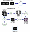
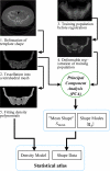
We propose a method for improving the quality of cone-beam tomographic reconstruction done with a C-arm. C-arm scans frequently suffer from incomplete information due to image truncation, limited scan length, or other limitations. Our proposed "hybrid reconstruction" method injects information from a prior anatomical model, derived from a subject-specific computed tomography (CT) or from a statistical database (atlas), where the C-arm X-ray data is missing. This significantly reduces reconstruction artifacts with little loss of true information from the X-ray projections. The methods consist of constructing anatomical models, fast rendering of digitally reconstructed radiograph (DRR) projections of the models, rigid or deformable registration of the model and the X-ray images, and fusion of the DRR and X-ray projections, all prior to a conventional filtered back-projection algorithm. Our experiments, conducted with a mobile image intensifier C-arm, demonstrate visually and quantitatively the contribution of data fusion to image quality, which we assess through comparison to a "ground truth" CT. Importantly, we show that a significantly improved reconstruction can be obtained from a C-arm scan as short as 90° by complementing the observed projections with DRRs of two prior models, namely an atlas and a preoperative same-patient CT. The hybrid reconstruction principles are applicable to other types of C-arms as well.
Figures


Similar articles
-
A software tool of digital tomosynthesis application for patient positioning in radiotherapy.J Appl Clin Med Phys. 2016 Mar 8;17(2):174-193. doi: 10.1120/jacmp.v17i2.5999. J Appl Clin Med Phys. 2016. PMID: 27074482 Free PMC article.
-
A three-dimensional weighted cone beam filtered backprojection (CB-FBP) algorithm for image reconstruction in volumetric CT under a circular source trajectory.Phys Med Biol. 2005 Aug 21;50(16):3889-905. doi: 10.1088/0031-9155/50/16/016. Epub 2005 Aug 2. Phys Med Biol. 2005. PMID: 16077234
-
Statistical shape model-based reconstruction of a scaled, patient-specific surface model of the pelvis from a single standard AP x-ray radiograph.Med Phys. 2010 Apr;37(4):1424-39. doi: 10.1118/1.3327453. Med Phys. 2010. PMID: 20443464
-
Accelerating reconstruction of reference digital tomosynthesis using graphics hardware.Med Phys. 2007 Oct;34(10):3768-76. doi: 10.1118/1.2779945. Med Phys. 2007. PMID: 17985622
-
A Review on Fast Tomographic Imaging Techniques and Their Potential Application in Industrial Process Control.Sensors (Basel). 2022 Mar 16;22(6):2309. doi: 10.3390/s22062309. Sensors (Basel). 2022. PMID: 35336477 Free PMC article. Review.
Cited by
-
A method of 2D/3D registration of a statistical mouse atlas with a planar X-ray projection and an optical photo.Med Image Anal. 2013 May;17(4):401-16. doi: 10.1016/j.media.2013.02.009. Epub 2013 Mar 5. Med Image Anal. 2013. PMID: 23542374 Free PMC article.
-
Deformable registration of CT and cone-beam CT with local intensity matching.Phys Med Biol. 2017 Feb 7;62(3):927-947. doi: 10.1088/1361-6560/aa4f6d. Epub 2017 Jan 11. Phys Med Biol. 2017. PMID: 28074785 Free PMC article.
-
3D-2D registration for surgical guidance: effect of projection view angles on registration accuracy.Phys Med Biol. 2014 Jan 20;59(2):271-87. doi: 10.1088/0031-9155/59/2/271. Epub 2013 Dec 19. Phys Med Biol. 2014. PMID: 24351769 Free PMC article.
-
Probabilistic evaluation of three-dimensional reconstructions from X-ray images spanning a limited angle.Sensors (Basel). 2012 Dec 21;13(1):137-51. doi: 10.3390/s130100137. Sensors (Basel). 2012. PMID: 23344378 Free PMC article.
-
An active contour method for bone cement reconstruction from C-arm x-ray images.IEEE Trans Med Imaging. 2012 Apr;31(4):860-9. doi: 10.1109/TMI.2011.2171498. Epub 2011 Oct 13. IEEE Trans Med Imaging. 2012. PMID: 21997251 Free PMC article.
References
-
- Feldkamp LA, Davis LC, Kress JW. Practical cone-beam algorithm. Journal of the Optical Society of America A (JOSA A) 1984 Jun;1(6):612–619.
-
- Sadowsky O, Ramamurthi K, Ellingsen LM, Chintalapani G, Prince JL, Taylor RH. IEEE International Symposium on Biomedical Imaging (ISBI) IEEE; 2006. Atlas-assisted tomography: registration of a deformable atlas to compensate for limited-angle cone-beam trajectory; pp. 1244–1247.
-
- Lewitt RM. Processing of incomplete measurement data in computed tomography. Medical Physics. 1979 Sep.6(5):412–417. - PubMed
-
- Hsieh J, Chao E, Thibault J, Grekowicz B, Horst A, McOlash S, Myers TJ. A novel reconstruction algorithm to extend the ct scan field-of-view. Medical Physics. 2004 Sep.31(9):2385–2391. - PubMed
Publication types
MeSH terms
Grants and funding
LinkOut - more resources
Full Text Sources
Other Literature Sources
Medical

