Review
. 2010 Nov;39(11):4326-54.
doi: 10.1039/b915139g. Epub 2010 Aug 9.

Designing multifunctional quantum dots for bioimaging, detection, and drug delivery

Affiliations
Review

Designing multifunctional quantum dots for bioimaging, detection, and drug delivery

Pavel Zrazhevskiy et al. Chem Soc Rev. 2010 Nov.

Abstract

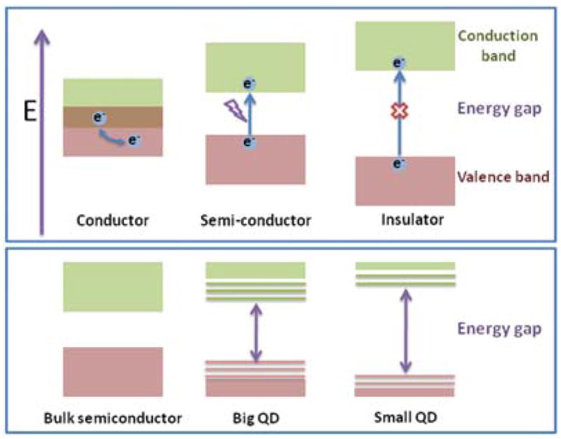
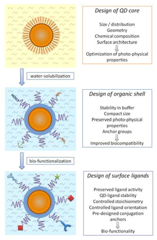
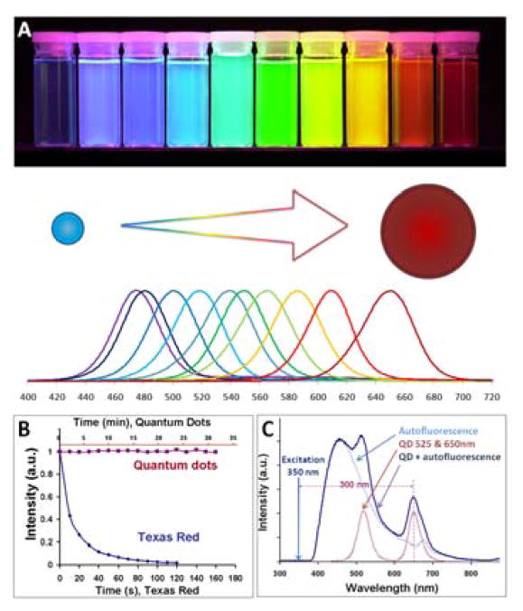
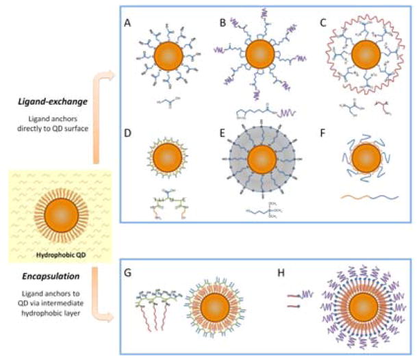
The emerging field of bionanotechnology aims at revolutionizing biomedical research and clinical practice via introduction of nanoparticle-based tools, expanding capabilities of existing investigative, diagnostic, and therapeutic techniques as well as creating novel instruments and approaches for addressing challenges faced by medicine. Quantum dots (QDs), semiconductor nanoparticles with unique photo-physical properties, have become one of the dominant classes of imaging probes as well as universal platforms for engineering of multifunctional nanodevices. Possessing versatile surface chemistry and superior optical features, QDs have found initial use in a variety of in vitro and in vivo applications. However, careful engineering of QD probes guided by application-specific design criteria is becoming increasingly important for successful transition of this technology from proof-of-concept studies towards real-life clinical applications. This review outlines the major design principles and criteria, from general ones to application-specific, governing the engineering of novel QD probes satisfying the increasing demands and requirements of nanomedicine and discusses the future directions of QD-focused bionanotechnology research (critical review, 201 references).


Figures

Fig. 1
Fig. 1
Electronic structure of bulk conductor, semiconductor, and insulator materials (top panel) and semiconductor nanoparticles (bottom panel). Bulk semiconductor materials have fully populated valence band and empty conduction band separated by a relatively small band gap. When an energy exciding the band gap is supplied, valence-band electrons acquire sufficient energy to populate conduction band and enable electric current flow. In nanoparticles, valence and conduction bands split into discrete energy levels, with the energy gap between closest possible valence and conduction levels increasing with decreasing particle size (and increasing degree of confinement of charge carriers).
Fig. 2
Fig. 2
General steps and design criteria in engineering of QD probes for biomedical applications.
Fig. 3
Fig. 3
Unique photo-physical properties of QD probes. A) Narrow size-tunable light emission profile enables precise control over the probe color via varying the nanoparticle size. B) Outstanding photostability of QDs enables real-time monitoring of probe dynamics and accurate quantitative analysis, whereas quick photobleaching of organic dyes limits such applications. C) Capability of absorbing high-energy (UV-blue) light without damaging the probe and emitting fluorescence with a large Stokes shift enables efficient separation of the QD signal over the fluorescent background. Reprinted from ref. , Copyright (2005), with permission from Elsevier.
Fig. 4
Fig. 4
Routes for water-solubilization of hydrophobic QDs. Ligand-exchange procedures (A–F) involve replacing the native hydrophobic surface ligands (e.g. TOPO) with hydrophilic ones by direct anchoring of ligands to the QD surface. (G–H) Encapsulation procedures preserve the native QD surface structure and over-coat QDs with amphiphilic molecules (such as polymers or lipids) via hydrophobic interactions.
Fig. 5
Fig. 5
Routes for QD bio-functionalization. Decoration of QD surface with bio-ligands can be achieved via covalent conjugation (A, B), non-covalent coordination of thiol groups or polyhistidine tags with the QD surface metal atoms (C), or electrostatic deposition of charged molecules on the QD organic shell (D).
Fig. 6
Fig. 6
Labeling of surface and intracellular targets with QD probes. In single-color examples membrane-associated Her2 receptors are detected with primary antibodies and QD-labeled secondary IgG (A, green), while intracellular nuclear antigens (B, red) and microtubules (C, red) are visualized with primary IgG/secondary IgG-biotin/QD-Streptavidin cascade. Both labeling routes can be applied simultaneously for a two-color staining (D). The nuclei are counter-stained with Hoechst 33342 (blue) in A and C. Reprinted by permission from Macmillan Publishers Ltd., copyright (2003).
Fig. 7
Fig. 7
Multiplexed labeling of breast cancer tissue biopsies. Normalization of the fluorescence according to relative QD intensities is required for accurate quantitative analysis of biomarker expression. Reproduced with permission from ref. . Copyright 2007 Wiley-VCH Verlag GmbH & Co. KGaA.
Fig. 8
Fig. 8
Labeling of individual glycine receptors in cultured spinal neurons. QD probes label glycine receptors throughout somatodendritic compartment (A) and can be located adjacent to (B, arrowhead) or in front of (B, arrow) inhibitory synaptic boutons. TEM examination reveals QD clustering at the extrasynaptic (C), perisynaptic (D), and synaptic (E) regions. Reprinted from ref. with permission from AAAS. Copyright (2008).
Fig. 9
Fig. 9
Labeling of erbB/Her transmembrane receptors with QD-EGF probes. Continuous observation of QDs in live cells enabled monitoring of receptor heterodimerization, probe endocytosis, and QD-EGF retrograde transport along cell filopodia. Reprinted by permission from Macmillan Publishers Ltd., copyright (2004).
Fig. 10
Fig. 10
Mechanical (A–C) and non-mechanical (D–F) routes for intracellular delivery of bio-functional QDs within live cells. A) Microinjection enables intracellular loading of unmodified QD probes along with carrier solution on a cell-by-cell basis. B) Delivery with nanotubes offers precise control over QD delivery location, but requires QD anchoring to nanotubes via reducible linkers. C) High-throughput microinjection via nanosyringe arrays delivers unmodified QDs within large cell population, but changes the surface topology for cell growth. D) QDs functionalized with cell-penetrating peptides might employ endosome-mediated and non-endosomal pathways (depending on the peptide structure), offering flexibility in tuning the QD-cell interaction. E) Pinocytosis enables uptake of unmodified QD probes with consequent cytoplasmic distribution. F) Utilization of active receptor-mediated QD uptake via endocytosis followed by endosomal escape via proton-sponge effect represents a highly efficient non-invasive delivery method with specific targeting capabilities.
Fig. 11
Fig. 11
Two-photon (top panel) and one-photon (bottom panel) excitation of QD-Cy3 FRET system. QDs are efficiently excited by both methods, enabling fluorescence of conjugated Cy3 molecules via FRET. However, only two-photon excitation precludes non-FRET excitation of Cy3 dye, whereas conventional one-photon fluorescence imaging produces significant background via direct Cy3 excitation. Reproduced with permission from ref. . Copyright 2007 Wiley-VCH Verlag GmbH & Co. KGaA.
Fig. 12
Fig. 12
Potential routes for elimination of Cd-associated QD toxicity.
Fig. 13
Fig. 13
In vivo imaging of blood vasculature with QDs. Large QDs remain within the blood vessels providing good image contrast (A), whereas FITC-labeled dextran quickly extravasates creating high background (B). Two-photon microscopy enables deeper-tissue imaging with QDs, highlighting not only the superficial vasculature (C), but also capillary network up to 250 μm deep within the tissue (D). Reprinted from ref. with permission from AAAS. Copyright (2003).
Fig. 14
Fig. 14
Sentinel lymph node mapping with NIR QDs. Intradermally injected QDs efficiently accumulate in SLN, enabling SLN visualization through the skin and image-guided lymph node resection. Reprinted by permission from Macmillan Publishers Ltd., copyright (2004).
Fig. 15
Fig. 15
Sequential mapping of several lymph nodes with compact QDs. Small size enables QD probes to escape SLN and travel along the lymphatic system to distant lymph nodes. Reprinted with permission from ref. . Copyright 2006 American Chemical Society.
Fig. 16
Fig. 16
Multiplexed in vivo and ex vivo imaging of separate lymphatic networks with QD accumulation in SLNs. Reprinted with permission from ref. . Copyright 2007 American Chemical Society.
Fig. 17
Fig. 17
In vivo imaging of implanted QD-tagged tumor cells. A) Bright QD tags (B) enable visualization of tumor cells through skin with a non-invasive whole-animal fluorescence imaging, whereas organic dye (C) signal is indistinguishable from autofluorescence. C) Imaging of subcutaneously implanted QD-loaded microbeads shows the potential for multiplexed in vivo cell detection and tracking. Reprinted by permission from Macmillan Publishers Ltd., copyright (2004).
Fig. 18
Fig. 18
Intravital tracking of a single bone marrow-derived progenitor cell. Seven images taken with 1 second intervals are superimposed to show the movement of a QD-labeled cell (red) through a tumor blood vessel. Vasculature is highlighted with blue QDs. Reprinted by permission from Macmillan Publishers Ltd., copyright (2005).
Fig. 19
Fig. 19
3-dimensional tracking of dye-labeled haematopoietic cells (white) within bone marrow. QDs outline the vasculature, while bone collagen is visualized with second harmonic generation (blue) and osteoblasts - via GFP fluorescence (green). 3-D reconstruction enables detailed study of bone marrow structure and precise localization of cells within their niches. Reprinted by permission from Macmillan Publishers Ltd., copyright (2008).
Fig. 20
Fig. 20
In vivo imaging of self-illuminating QD probes. QDs excited via bioluminescence resonance energy transfer from conjugated luciferase are clearly visible with non-invasive whole-animal imaging (A), whereas the signal from same probes illuminated by an external short-wavelength excitation source is indistinguishable from the strong tissue autofluorescence (B). Reprinted by permission from Macmillan Publishers Ltd., copyright (2006).
Fig. 21
Fig. 21
Routes for in vivo QD targeting. A) Abnormal highly permeable tumor blood vasculature and poor tumor lymphatic drainage enable passive QD targeting and accumulation within the tumor via enhanced permeability and retention effect. Similar mechanism can be employed for labeling the regions with damaged or abnormal vasculature. B) Intact endothelium represents a significant barrier for QD extravasation. Labeling of biomarkers specifically expressed on the vasculature of a particular organ or tissue (e.g. tumor site) provides an efficient way of targeted in vivo imaging with bulky QD probes. C) When QD extravasation is possible, active targeting of biomarkers expressed on the cell surface enables specific labeling deep within the tissues of interest, while reducing non-specific QD accumulation in non-targeted areas.
Fig. 22
Fig. 22
Engineering of QD-based nanocomposites for dual-modal imaging. Fluorescence/MRI probes can be prepared by synthesizing QD-MNP heterostructures (A) or incorporating QDs and paramagnetic compounds (e.g. Gd chelates) either within larger nanostructures (B) or on a single-QD platform (C). Fluorescence/PET probes can be made by functionalizing the QD surface with radionuclides (e.g. 64Cu) along with other targeting and therapeutic moieties (D). Plasmonic fluorescent probes incorporate gold nanoparticles and nanospheres either directly attached to the QD surface or grown around the QD in the form of shell (E).
Fig. 23
Fig. 23
Engineering of QD-based therapeutic nanocomposites. QDs can be used as tags for labeling of larger drug carriers, such as liposomes (A, B) and polymeric nanoparticles (C), or as single-QD platforms for traceable drug loading and delivery (D–F).

Similar articles

Cited by

References

    1. Nanoscale Science Engineering and Technology Subcommittee (NSET), Committee on Technology (CT) and National Science and Technology Council (NSTC) Vol. 44 2009.
    1. Chen H, Roco MC, Li X, Lin Y. Nat Nanotechnol. 2008;3:123–125. - PubMed
    1. Massoud TF, Gambhir SS. Genes & development. 2003;17:545–580. - PubMed
    1. Mankoff DA. J Nucl Med. 2007;48:18N–21N. - PubMed
    1. Medintz IL, Mattoussi H. Phys Chem Chem Phys. 2009;11:17–45. - PubMed

Publication types