

doi: 10.1155/2010/659802.
Epub 2010 Jul 18.
Development of 3D CAD/FEM Analysis System for Natural Teeth and Jaw Bone Constructed from X-Ray CT Images
Affiliations
- PMID: 20706535
- PMCID: PMC2913519
- DOI: 10.1155/2010/659802
Item in Clipboard
Development of 3D CAD/FEM Analysis System for Natural Teeth and Jaw Bone Constructed from X-Ray CT Images
Int J Biomater.
2010.
Abstract
A three-dimensional finite element model of the lower first premolar, with the three layers of enamel, dentin, and pulp, and the mandible, with the two layers of cortical and cancellous bones, was directly constructed from noninvasively acquired CT images. This model was used to develop a system to analyze the stresses on the teeth and supporting bone structure during occlusion based on the finite element method and to examine the possibility of mechanical simulation.
Figures
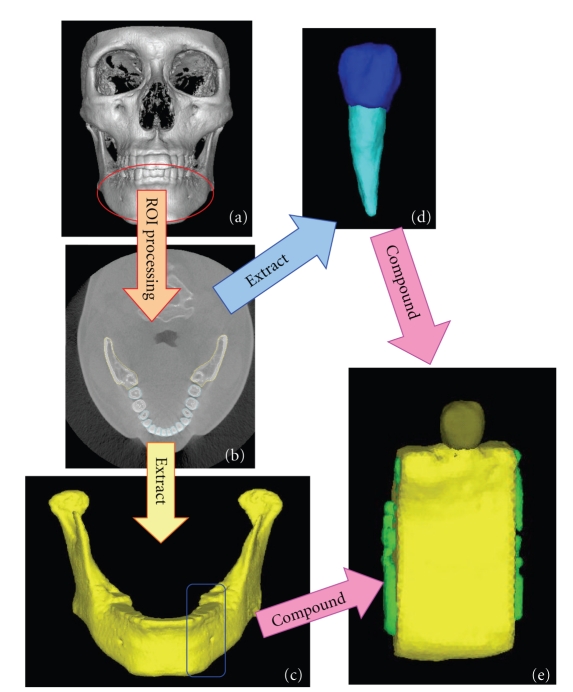
Flow of procedure for the FE modeling of the mandibular bone and tooth by MF. (a) CT scan of the testee, (b) extracting bone lines, (c) mandibular bone, (d) tooth, (e) 3D FE models.
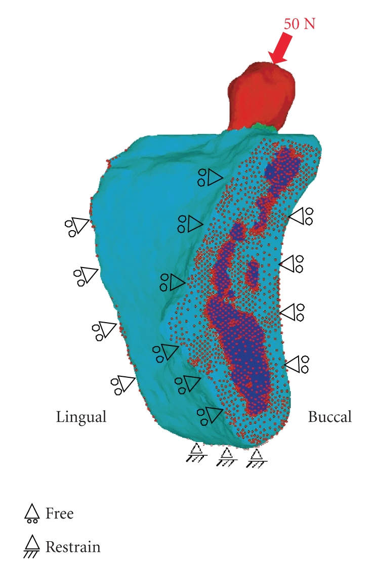
Geometrical and boundary conditions. A buccolingual force at a 45-degree oblique angle to the tooth axis was concentrated onto a single contact point, and static occlusal load of 50 N was applied to the premolar buccal cusp of teeth. Inferior border of the mandible was assumed to be fixed.
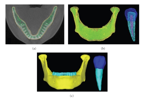
Geometry of 3D images and 3D models. (a) ROI of CT image, (b) 3D solid model, (c) 3D FE models.
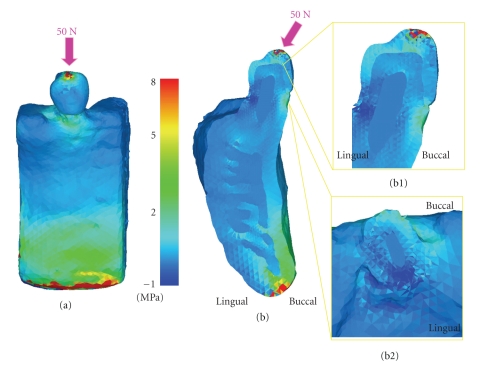
Maximum principal stress distribution. (a) Buccal view, (b) Buccolingual cross-section, (b1) Magnify of Buccolingual cross-section, (b2) Magnify of horizontal cross-section at the cervical.
Similar articles
-
Creation of a three-dimensional model of the mandible and the TMJ in vivo by means of the finite element method.Int J Comput Dent. 2002 Apr-Jul;5(2-3):87-99. Int J Comput Dent. 2002. PMID: 12680039 English, Spanish.
-
[Analysis of the effect of mesial implant position on surrounding bone stress of mandibular edentulous jaw under dynamic loads].Zhonghua Kou Qiang Yi Xue Za Zhi. 2017 Nov 9;52(11):672-677. doi: 10.3760/cma.j.issn.1002-0098.2017.11.005. Zhonghua Kou Qiang Yi Xue Za Zhi. 2017. PMID: 29972946 Chinese.
-
Effect of the crown design and interface lute parameters on the stress-state of a machined crown-tooth system: a finite element analysis.Dent Mater. 2013 Aug;29(8):e123-31. doi: 10.1016/j.dental.2013.04.002. Epub 2013 May 23. Dent Mater. 2013. PMID: 23706694
-
Stresses in mandibular cortical bone during mastication: biomechanical considerations using a three-dimensional finite element method.J Oral Sci. 2002 Mar;44(1):1-6. doi: 10.2334/josnusd.44.1. J Oral Sci. 2002. PMID: 12058864
-
Dental application of novel finite element analysis software for three-dimensional finite element modeling of a dentulous mandible from its computed tomography images.Proc Inst Mech Eng H. 2013 Dec;227(12):1312-8. doi: 10.1177/0954411913508054. Epub 2013 Sep 27. Proc Inst Mech Eng H. 2013. PMID: 24077258
Cited by
-
The evolutionary paradox of tooth wear: simply destruction or inevitable adaptation?PLoS One. 2013 Apr 24;8(4):e62263. doi: 10.1371/journal.pone.0062263. Print 2013. PLoS One. 2013. PMID: 23638020 Free PMC article.
-
Comparison of occlusal loading conditions in a lower second premolar using three-dimensional finite element analysis.Clin Oral Investig. 2014;18(2):369-75. doi: 10.1007/s00784-013-0973-8. Epub 2013 Mar 16. Clin Oral Investig. 2014. PMID: 23504207
-
The Integration of Micro-CT Imaging and Finite Element Simulations for Modelling Tooth-Inlay Systems for Mechanical Stress Analysis: A Preliminary Study.J Funct Biomater. 2025 Jul 21;16(7):267. doi: 10.3390/jfb16070267. J Funct Biomater. 2025. PMID: 40710481 Free PMC article.
-
Comparative Numerical Analysis between Two Types of Orthodontic Wire for the Lingual Technique, Using the Finite Element Method.Appl Bionics Biomech. 2021 Mar 25;2021:6658039. doi: 10.1155/2021/6658039. eCollection 2021. Appl Bionics Biomech. 2021. PMID: 33833825 Free PMC article.
-
The adaptive significance of enamel loss in the mandibular incisors of cercopithecine primates (Mammalia: Cercopithecidae): a finite element modelling study.PLoS One. 2014 May 15;9(5):e97677. doi: 10.1371/journal.pone.0097677. eCollection 2014. PLoS One. 2014. PMID: 24831704 Free PMC article.
References
-
- Benzing UR, Gall H, Weber H. Biomechanical aspects of two different implant-prosthetic concepts for edentulous maxillae. International Journal of Oral & Maxillofacial Implants. 1995;10(2):188–198. - PubMed
-
- Cibirka RM, Razzoog ME, Lang BR, Stohler CS. Determining the force absorption quotient for restorative materials used in implant occlusal surfaces. Journal of Prosthetic Dentistry. 1992;67(3):361–364. - PubMed
-
- Mahler DB, Peyton FA. Photoelasticity as a research technique for analyzing stresses in dental structures. Journal of Dental Research. 1955;34(6):831–838. - PubMed
-
- Helldén LB, Dérand T. Description and evaluation of a simplified method to achieve passive fit between cast titanium frameworks and implants. International Journal of Oral and Maxillofacial Implants. 1998;13(2):190–196. - PubMed
-
- Zarone F, Apicella A, Nicolais L, Aversa R, Sorrentino R. Mandibular flexure and stress build-up in mandibular full-arch fixed prostheses supported by osseointegrated implants. Clinical Oral Implants Research. 2003;14(1):103–114. - PubMed
LinkOut - more resources
Full Text Sources
Miscellaneous
