

Dosimetric assessment of rigid setup error by CBCT for HN-IMRT
- PMID: 20717085
- PMCID: PMC5720430
- DOI: 10.1120/jacmp.v11i3.3187
Dosimetric assessment of rigid setup error by CBCT for HN-IMRT
Abstract
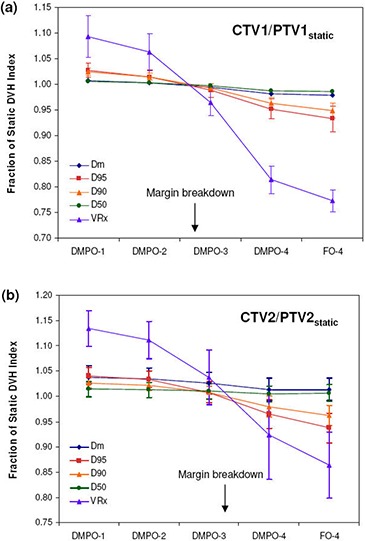
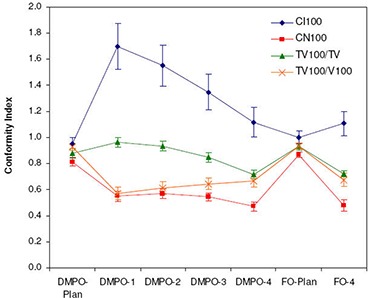
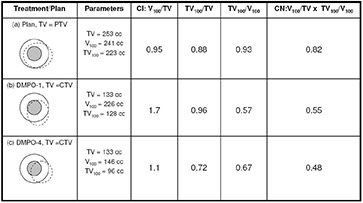
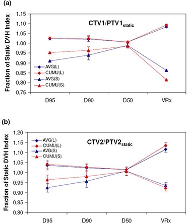
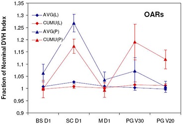
Dose distributions in HN-IMRT are complex and may be sensitive to the treatment uncertainties. The goals of this study were to evaluate: 1) dose differences between plan and actual delivery and implications on margin requirement for HN-IMRT with rigid setup errors; 2) dose distribution complexity on setup error sensitivity; and 3) agreement between average dose and cumulative dose in fractionated radiotherapy. Rigid setup errors for HN-IMRT patients were measured using cone-beam CT (CBCT) for 30 patients and 896 fractions. These were applied to plans for 12HN patients who underwent simultaneous integrated boost (SIB) IMRT treatment. Dose distributions were recalculated at each fraction and summed into cumulative dose. Measured setup errors were scaled by factors of 2-4 to investigate margin adequacy. Two plans, direct machine parameter optimization (DMPO) and fluence only (FO), were available for each patient to represent plans of different complexity. Normalized dosimetric indices, conformity index (CI) and conformation number (CN) were used in the evaluation. It was found that current 5 mm margins are more than adequate to compensate for rigid setup errors, and that standard margin recipes overestimate margins for rigid setup error in SIB HN-IMRT because of differences in acceptance criteria used in margin evaluation. The CTV-to-PTV margins can be effectively reduced to 1.9 mm and 1.5 mm for CTV1 and CTV2. Plans of higher complexity and sharper dose gradients are more sensitive to setup error and require larger margins. The CI and CN are not recommended for cumulative dose evaluation because of inconsistent definition of target volumes used. For fractionated radiotherapy in HN-IMRT, the average fractional dose does not represent the true cumulative dose received by the patient through voxel-by-voxel summation, primarily due to the setup error characteristics, where the random component is larger than systematic and different target regions get underdosed at each fraction.
Figures


Similar articles
-
Effect of patient setup errors on simultaneously integrated boost head and neck IMRT treatment plans.Int J Radiat Oncol Biol Phys. 2005 Oct 1;63(2):422-33. doi: 10.1016/j.ijrobp.2005.02.029. Int J Radiat Oncol Biol Phys. 2005. PMID: 16168835
-
Evaluation of dosimetric margins in prostate IMRT treatment plans.Med Phys. 2008 Feb;35(2):569-75. doi: 10.1118/1.2826558. Med Phys. 2008. PMID: 18383678 Free PMC article.
-
Dosimetric influences of rotational setup errors on head and neck carcinoma intensity-modulated radiation therapy treatments.Med Dosim. 2013 Summer;38(2):125-32. doi: 10.1016/j.meddos.2012.09.003. Epub 2012 Dec 21. Med Dosim. 2013. PMID: 23266161 Clinical Trial.
-
PTV margin analysis for prostate patients treated with initial pelvic nodal IMRT and prostate proton boost.Phys Med Biol. 2019 Feb 8;64(4):04NT04. doi: 10.1088/1361-6560/aafd75. Phys Med Biol. 2019. PMID: 30630135
-
Adaptive optimization by 6 DOF robotic couch in prostate volumetric IMRT treatment: rototranslational shift and dosimetric consequences.J Appl Clin Med Phys. 2015 Sep 8;16(5):35-45. doi: 10.1120/jacmp.v16i5.5525. J Appl Clin Med Phys. 2015. PMID: 26699314 Free PMC article. Review.
Cited by
-
Deformable image registration and interobserver variation in contour propagation for radiation therapy planning.J Appl Clin Med Phys. 2016 May 8;17(3):347-357. doi: 10.1120/jacmp.v17i3.6110. J Appl Clin Med Phys. 2016. PMID: 27167289 Free PMC article.
References
-
- Longobardi B, De Martin E, Fiorino C, et al. Comparing 3DCRT and inversely optimized IMRT planning for head and neck cancer: equivalence between step‐and‐shoot and sliding window techniques. Radiother Oncol. 2005;77(2):148–56. - PubMed
-
- Vergeer MR, Doornaert PA, Rietveld DH, Leemans CR, Stotman BJ, Langendijk JA. Intensity‐modulated radiotherapy reduces radiation‐induced morbidity and improves health‐related quality of life: results of a nonrandomized prospective study using a standardized follow‐up program. Int J Radiat Oncol Biol Phys. 2009;74(1):1–8. - PubMed
-
- Samuelsson A, Mercke C, Johansson KA. Systematic set‐up errors for IMRT in the head and neck region: effect on dose distribution. Radiother Oncol. 2003;66(3):303–11. - PubMed
-
- International Commission on Radiation Units and Measurements (ICRU) . Prescribing, recording and reporting photon beam therapy. ICRU Report 50. Bethesda, MD: ICRU; 1994.
-
- International Commission on Radiation Units and Measurements (ICRU) . Prescribing, recording and reporting photon beam therapy (Supplement to ICRU Report 50). ICRU Report 62. Bethesda, MD: ICRU; 2000.
Publication types
MeSH terms
LinkOut - more resources
Full Text Sources
