

doi: 10.1364/OE.18.018086.
Temporally focused femtosecond laser pulses for low numerical aperture micromachining through optically transparent materials
Affiliations
- PMID: 20721196
- PMCID: PMC3408926
- DOI: 10.1364/OE.18.018086
Item in Clipboard
Temporally focused femtosecond laser pulses for low numerical aperture micromachining through optically transparent materials
Opt Express.
.
Abstract
Temporal focusing of spatially chirped femtosecond laser pulses overcomes previous limitations for ablating high aspect ratio features with low numerical aperture (NA) beams. Simultaneous spatial and temporal focusing reduces nonlinear interactions, such as self-focusing, prior to the focal plane so that deep (approximately 1 mm) features with parallel sidewalls are ablated at high material removal rates (25 microm(3) per 80 microJ pulse) at 0.04-0.05 NA. This technique is applied to the fabrication of microfluidic devices by ablation through the back surface of thick (6 mm) fused silica substrates. It is also used to ablate bone under aqueous immersion to produce craniotomies.
Figures
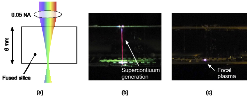
Basic utility of temporal focusing for micromachining. (a) An illustration of the focusing geometry. 800 nm, 60 fs, 50 µJ pulses are focused at 0.05 NA at the back surface of a 6 mm thick block of fused silica. (b) Without spatially chirped pulses, self-focusing and supercontinuum generation result in a loss of intensity at the focus. The glass is tracked along the length of the filament and selective ablation at the focal depth is inhibited. (c) With spatially chirped pulses, self-focusing and continuum generation are suppressed, and the backside of the glass sample is ablated as evidenced by the plasma emission.
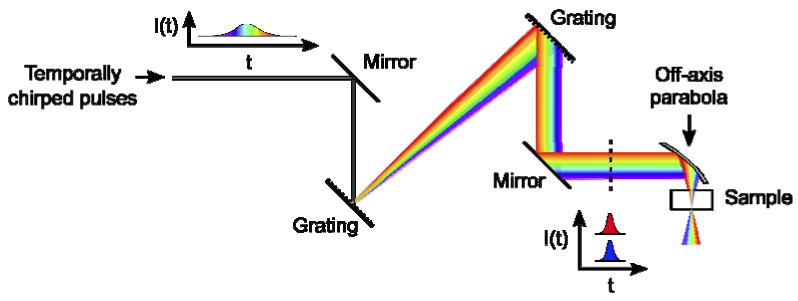
Scheme for temporal focusing of chirped pulses. The temporally chirped pulses are spatially chirped then collimated by two gratings. After the second grating, the intensities, I, of all frequencies overlap in time, t, but the frequencies do not overlap spatially except at the focal plane.
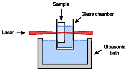
The sample is mounted in a transparent glass chamber. The chamber is filled with water and partially immersed in an ultrasonic bath.
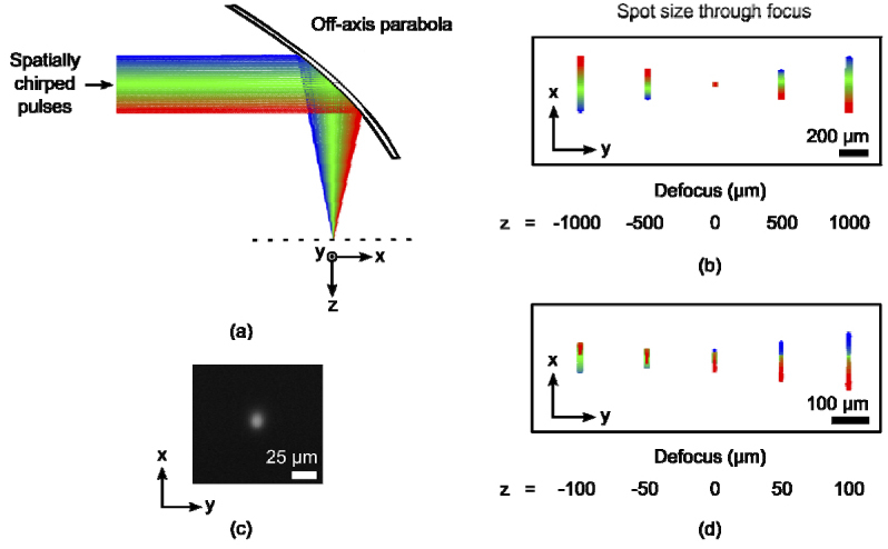
Geometric optics model. (a) The beam was ray-traced through the focus of a 25 mm focal length, 90 degree off-axis parabola. The center wavelength and the FWHM edges of the spectrum were represented by green, blue and red rays, respectively. (b) The shape of the beam spot in x (chirped dimension) and y (unchirped dimension) was simulated at several axial positions through focus. At focus (z = 0) the beam spot was symmetric. (c) An image of the focal plasma in air. (d) The shape of the beam spot was asymmetric at focus with the addition of 6 mm of fused silica to simulate backside machining.
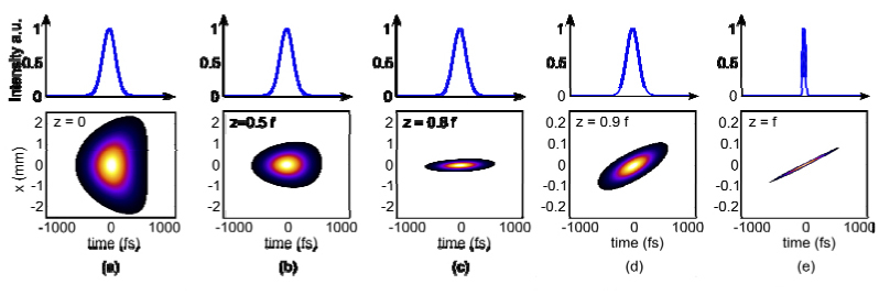
Spatio-temporal beam propagation. Beam propagation was simulated in the spatially chirped dimension, x, generated by Fourier pulse propagation using the non-paraxial propagator. We begin from (a) the lens at z = 0 and proceed in (b)-(e) to the focal plane at z = f. Note that the spatial scale has changed between (c) and (d) by a factor of 10. Above each spatio-temporal plot is a lineout at x = 0 with a corresponding temporal axis.
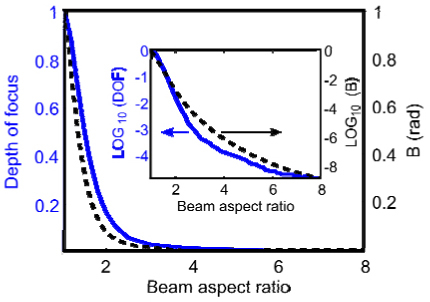
The depth of focus (DOF) and the B-integral as a function of the beam aspect ratio. All quantities are scaled by the value for an unchirped beam (BAR = 1).
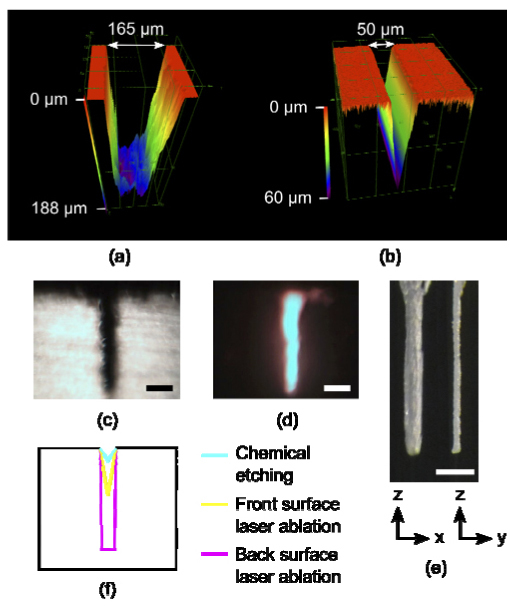
Confocal images of 200 µm long segments of microfluidic channels cut on (a) the backside with temporal focusing at 0.04 NA and on (b) the front side without temporal focusing at 0.07 NA. (c,d) Side-view white light and fluorescence images of a microfluidic channel cut on the backside with temporal focusing. (e) A hole was ablated into the back surface and imaged from two angles: the spatially chirped dimension (left) and the unchirped dimension (right). (c-e) Scale bar, 200 µm. (f) An illustration comparing channel cross sections for chemical etching with our measurements for front surface laser ablation and for back surface laser ablation.
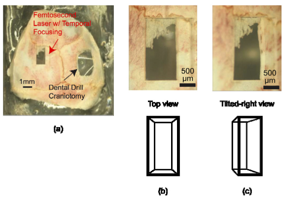
(a) Craniotomy in an excised mouse skull performed using femtosecond laser ablation with spatially chirped pulses (on left). For comparison, we show a traditional craniotomy performed with a hand-held dental drill (on right). The 1 mm wide × 2 mm long × 0.3 mm deep craniotomy was produced with less than 20 minutes of laser ablation. (b) Top and (c) tilted-right enlarged views of the femtosecond laser craniotomy.
References
-
- Hwang D. J., Choi T. Y., Grigoropoulos C. P., “Liquid-assisted femtosecond laser drilling of straight and three-dimensional microchannels in glass,” Appl. Phys., A Mater. Sci. Process. 79(3), 605–612 (2004).10.1007/s00339-004-2547-8 - DOI
Publication types
MeSH terms
Substances
Grants and funding
LinkOut - more resources
Full Text Sources
Other Literature Sources
