

A novel alignment device for cone beam computed tomography: principle and application
- PMID: 20729188
- PMCID: PMC3520241
- DOI: 10.1259/dmfr/21679313
A novel alignment device for cone beam computed tomography: principle and application
Abstract
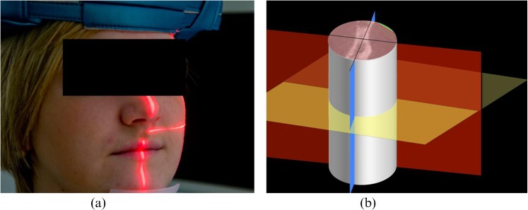
Objectives: the aim of this investigation was to optimize the positioning and size of the scanned field of view (FOV) in cone beam CT (CBCT) scanners using a practical external alignment device fitted in the patient's mouth in order to train radiographers and reduce radiation dose to the patient. This is particularly challenging when using small FOVs to cover small volumes of interest.
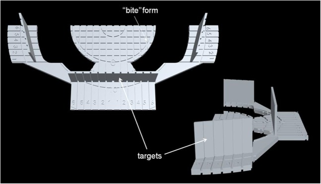
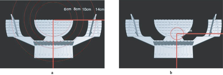
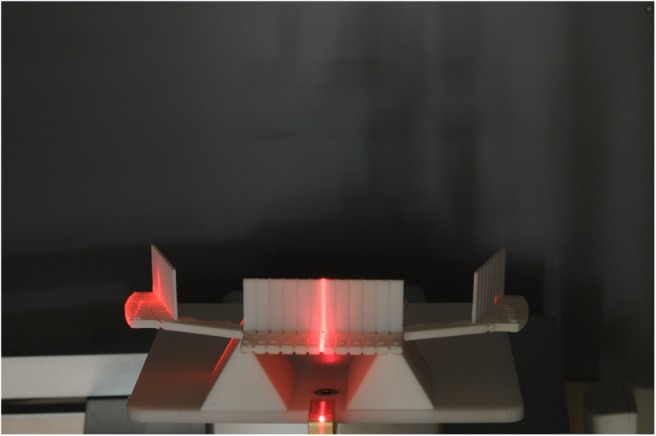
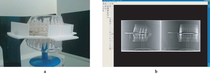
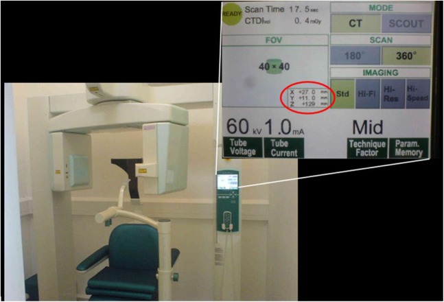
Methods: test objects were positioned and scanned using the aligner to show that the design and geometry were correct and help the radiographer to superimpose the scanner and the volume of interest axis of rotation. An in vivo study was then undertaken comparing the accuracy of patient positioning when using the aligner, instead of scouts, to position the patient for small FOV (cylinders of 4-8 cm height and 4-8 cm diameter) dental scans. The scanners used were the Accuitomo F170 CBCT scanner (Morita, Kyoto, Japan) and the iCAT Next Gen CBCT scanner (Imaging Sciences, Hatfield, PA).
Results: there was no significant difference in positioning the patient when using the aligner compared with the scout images.
Conclusions: it is possible to rely on the aligner for patient positioning for a small volume scan and therefore spare the radiation dose associated with scout imaging.
Figures
Similar articles
-
Effective radiation dose and eye lens dose in dental cone beam CT: effect of field of view and angle of rotation.Br J Radiol. 2014 Oct;87(1042):20130654. doi: 10.1259/bjr.20130654. Br J Radiol. 2014. PMID: 25189417 Free PMC article.
-
Cone beam computed tomography radiation dose and image quality assessments.Swed Dent J Suppl. 2010;(209):4-55. Swed Dent J Suppl. 2010. PMID: 21229915
-
Scatter-to-primary ratio in dentomaxillofacial cone-beam CT: effect of field of view and beam energy.Dentomaxillofac Radiol. 2021 Dec 1;50(8):20200597. doi: 10.1259/dmfr.20200597. Epub 2021 Apr 29. Dentomaxillofac Radiol. 2021. PMID: 33882256 Free PMC article.
-
Cone beam computed tomography in dentistry: Clinical recommendations and indication-specific features.J Dent. 2025 Aug;159:105781. doi: 10.1016/j.jdent.2025.105781. Epub 2025 Apr 23. J Dent. 2025. PMID: 40280537 Review.
-
Cone-beam computed tomography of the maxillofacial region--an update.Int J Med Robot. 2009 Dec;5(4):366-80. doi: 10.1002/rcs.279. Int J Med Robot. 2009. PMID: 19777550 Review.
Cited by
-
Minimum size and positioning of imaging field for CBCT scans of impacted maxillary canines.Clin Oral Investig. 2020 Feb;24(2):897-905. doi: 10.1007/s00784-019-02904-1. Epub 2019 Jun 24. Clin Oral Investig. 2020. PMID: 31236733
References
-
- Holberg C, Steinhauser S, Geis P, Rudzki-Janson I. Cone-beam computed tomography in orthodontics: benefits and limitations. J Orofac Orthop 2005;66:434–444 - PubMed
-
- Angelopoulos C. Cone beam tomographic imaging anatomy of the maxillofacial region. Dent Clin North Am 2008;52:731–752 - PubMed
-
- Patel S. New dimensions in endodontics imaging: part 2. Cone beam computed tomography. Int Endod J 2009;42:463–475 - PubMed
-
- White SC, Pharoah MJ. The evolution and application of dental maxillofacial imaging modalities. Dent Clin North Am 2008;52:689–705 - PubMed
-
- Palomo JM, Pejavar SR, Hans MG. Influence of CBCT exposure conditions on radiation dose. Oral Surg Oral Med Oral Pathol Oral Radiol Endod 2008;105:773–782 - PubMed
