

In vivo assessment of the impedance ratio method used in electronic foramen locators
- PMID: 20819212
- PMCID: PMC2944265
- DOI: 10.1186/1475-925X-9-46
In vivo assessment of the impedance ratio method used in electronic foramen locators
Abstract
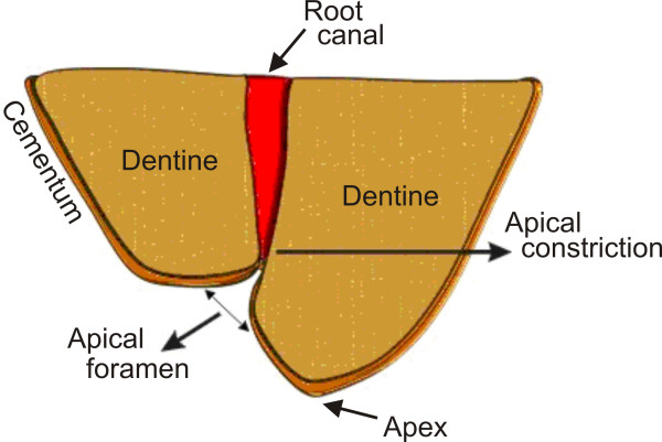
Background: The results of an in vivo study on the "ratio method" used in electronic foramen locators (EFL) are presented. EFLs are becoming widely used in the determination of the working length (WL) during the root canal treatment. The WL is the distance from a coronal reference point to the point at which canal preparation and filling should terminate. The "ratio method" was assessed by many clinicians with the aim of determining its ability to locate the apical foramen (AF). Nevertheless, in vivo studies to assess the method itself and to explain why the "ratio method" is able to locate the apical foramen and is unable to determine intermediate distances were not published so far.
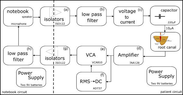
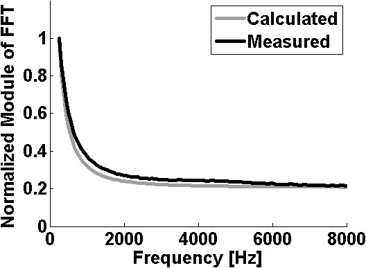
Methods: A developed apparatus applies an electrical current signal with constant amplitude of 10 μARMS through the endodontic file within the root canal. The applied current signal is composed by summing six sine waves, from 250 Hz to 8 kHz. Data were acquired with the endodontic file tip at 7 different positions within root canals. In the frequency domain the quotients between the amplitude of a reference frequency and the amplitudes of the other frequencies components were calculated. Twenty one root canals were analyzed in vivo, during the endodontic treatment of twelve teeth of different patients, with age between 20 to 55 years.
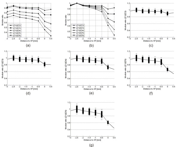
Results: For the range of frequencies used in the commercial EFLs and for distances ranging from -3 mm to -1 mm of the AF, the impedance of the root canal is mainly resistive. However, when the file tip gets closer to AF, the root canal electrical impedance starts to change from a mainly resistive to a complex impedance. This change in the measured root canal impedance starts when the file tip is near -1.0 mm from the AF, getting stronger as the file tip gets closer to the AF. This change in the impedance behavior affects the ratio (quotient) of the impedance measured at different frequencies. Through graphic analysis it is demonstrated why EFLs based on the ratio method are unable to accurately measure any distances between - 3.0 and -0.5 mm from the apical foramen. The only reliable measurement is the 0 mm distance, which is when the file tip is at the AF.
Conclusions: The electrical impedance values of 21 root canals were in vivo studied. The results confirm the ability of EFLs that are based on the ratio method to accurately locate the AF position and explain why they are unable to determine the file tip position along the root canal.
Figures
Similar articles
-
Accuracy of root canal length determination with the impedance ratio method.Int Endod J. 2009 Sep;42(9):819-26. doi: 10.1111/j.1365-2591.2009.01589.x. Epub 2009 Jun 22. Int Endod J. 2009. PMID: 19549150
-
Not all electronic foramen locators are accurate in teeth with enlarged apical foramina: an in vitro comparison of 5 brands.J Endod. 2014 Jan;40(1):109-12. doi: 10.1016/j.joen.2013.09.032. Epub 2013 Oct 25. J Endod. 2014. PMID: 24332000
-
Electrical impedance measurements of root canal length.Endod Dent Traumatol. 1997 Jun;13(3):126-31. doi: 10.1111/j.1600-9657.1997.tb00025.x. Endod Dent Traumatol. 1997. PMID: 9550026
-
Combination of apex locator and endodontic motor for continuous length control during root canal treatment.Int Endod J. 2009 Apr;42(4):368-74. doi: 10.1111/j.1365-2591.2008.01535.x. Epub 2009 Feb 7. Int Endod J. 2009. PMID: 19220512
-
The fundamental operating principles of electronic root canal length measurement devices.Int Endod J. 2006 Aug;39(8):595-609. doi: 10.1111/j.1365-2591.2006.01131.x. Int Endod J. 2006. PMID: 16872454 Review.
Cited by
-
Evaluation of electrical impedance ratio measurements in accuracy of electronic apex locators.Restor Dent Endod. 2015 May;40(2):113-22. doi: 10.5395/rde.2015.40.2.113. Epub 2014 Dec 26. Restor Dent Endod. 2015. PMID: 25984472 Free PMC article.
References
-
- American Association of Endodontists (AAE) Glossary of Endodontic Terms. 7. American Association of Endodontists, Chicago, IL; 2003.
-
- Ramo CAS, Bramante CM. Working length determination: fundamentals and techniques (Original title in Portuguese: "Odontometria: Fundamentos e Técnicas") Santos Livraria, São Paulo, Brasil. 2005.
Publication types
MeSH terms
LinkOut - more resources
Full Text Sources
