. 2010 Oct;7(10):848-54.
doi: 10.1038/nmeth.1505. Epub 2010 Sep 19.

Scanless two-photon excitation of channelrhodopsin-2

Affiliations

Scanless two-photon excitation of channelrhodopsin-2

Eirini Papagiakoumou et al. Nat Methods. 2010 Oct.

Abstract

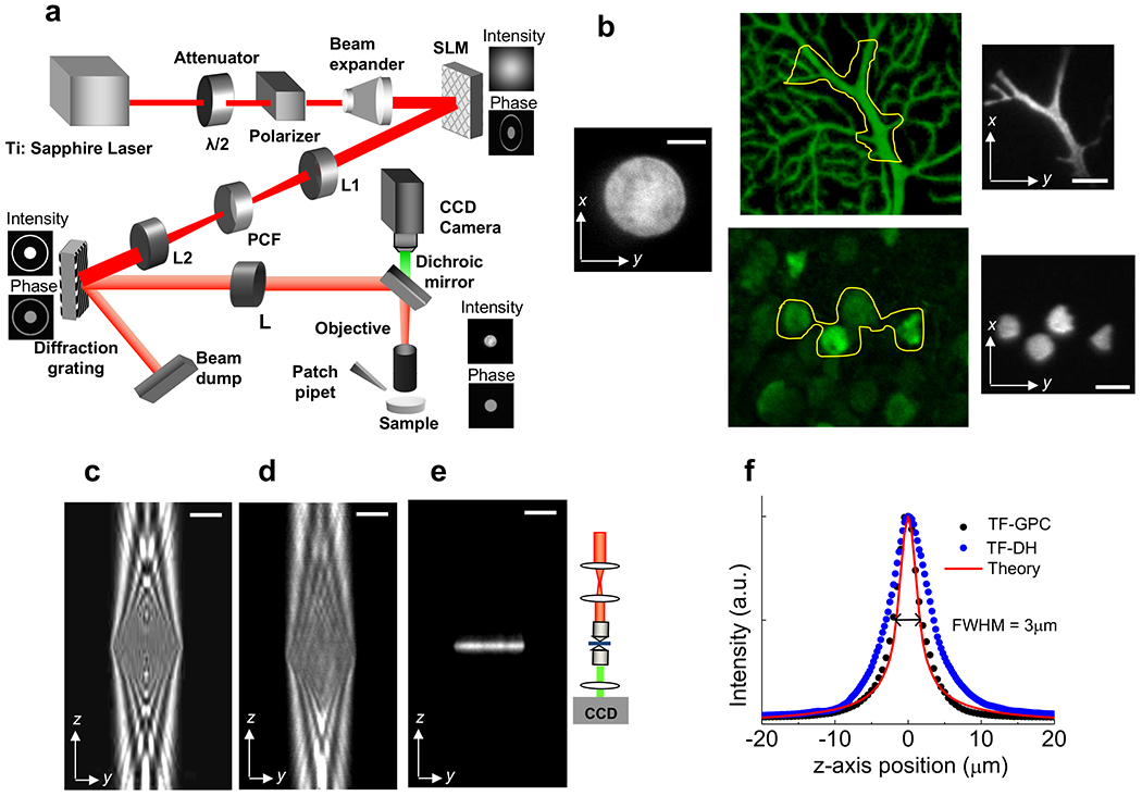
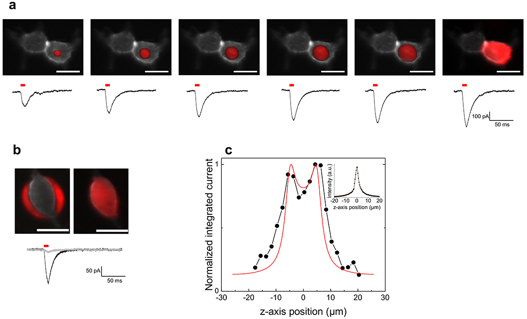
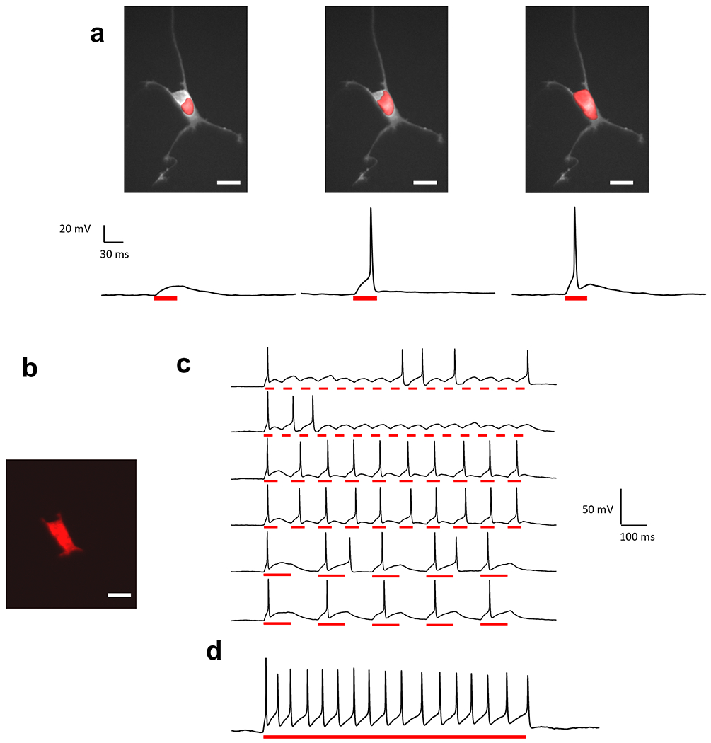
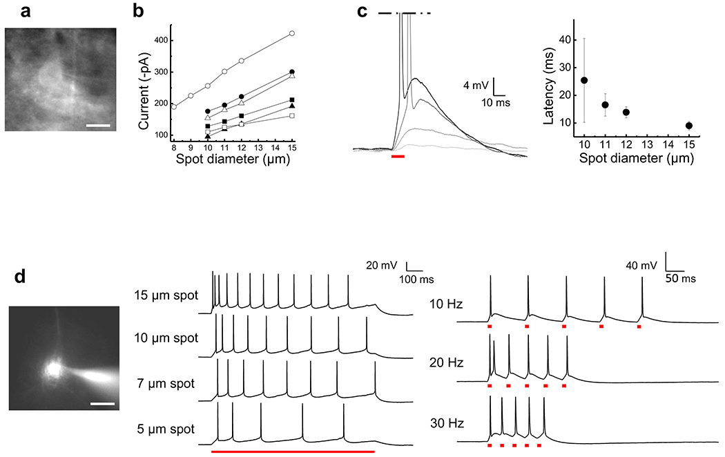
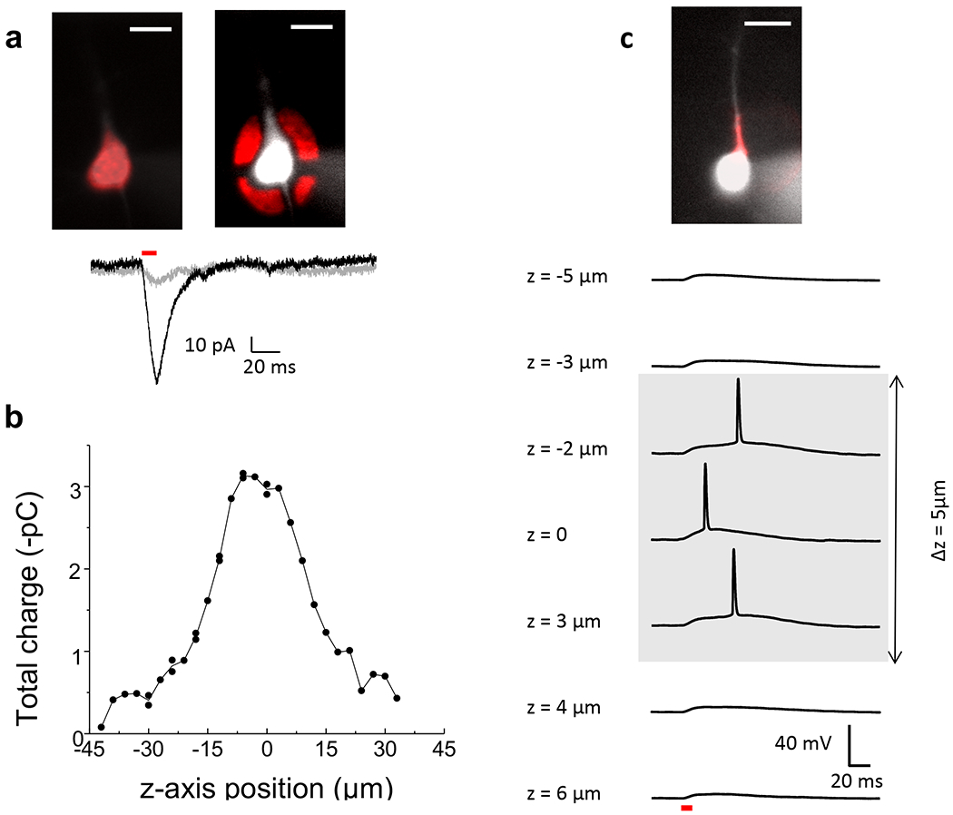
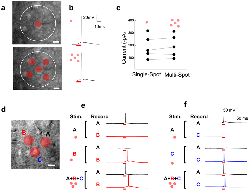
Light-gated ion channels and pumps have made it possible to probe intact neural circuits by manipulating the activity of groups of genetically similar neurons. What is needed now is a method for precisely aiming the stimulating light at single neuronal processes, neurons or groups of neurons. We developed a method that combines generalized phase contrast with temporal focusing (TF-GPC) to shape two-photon excitation for this purpose. The illumination patterns are generated automatically from fluorescence images of neurons and shaped to cover the cell body or dendrites, or distributed groups of cells. The TF-GPC two-photon excitation patterns generated large photocurrents in Channelrhodopsin-2-expressing cultured cells and neurons and in mouse acute cortical slices. The amplitudes of the photocurrents can be precisely modulated by controlling the size and shape of the excitation volume and, thereby, be used to trigger single action potentials or trains of action potentials.


Figures

Figure 1.
Figure 1.. Temporal focusing and generalized phase contrast.
Layout of the optical setup (Beam expander: 5×, SLM: Spatial Light Modulator, L1, L2, L: lenses with focal lengths f1 = 400 mm, f2 = 300 mm and f = 500 mm, PCF: Phase Contrast Filter, Diffraction Grating: 830 lines/mm, CCD: Camera). An example of the intensity and phase distributions at the SLM, grating and sample planes are indicated.
Figure 2.
Figure 2.. Lateral and axial control of the excitation volume.
(a) Images of a circular spot of diameter s = 20 μm and shaped patterns created with the setup illustrated in Fig. 1, by 2P excitation of a thin (~1 μm) fluorescent layer (excitation wavelength, λexc = 780 nm; objective 60×, 0.9 NA). The shaped patterns were designed on the basis of a confocal fluorescence image of a Purkinje cell (center up) and a wide-field fluorescence image of CA1 hippocampal neurons loaded with Oregon green bapta (center down), in selected regions of interest (yellow line), (b) Lateral profile of the 20 μm circular spot shown in a (black curve) compared to the lateral profile measured for a 20μm circular spot generated with digital holography (DH) (red line) from Papagiakoumou et al.. (c) y-z section of a simulated axial propagation of a GPC-generated 20 μm spot when temporal focusing (TF) is not applied to the system, (d) The same with c experimentally measured with a double microscope (inset), (e) y-z section of a measured axial propagation of a GPC-generated 20 μm spot when TF is applied, (f) Axial profile of the fluorescence intensity integrated over the different planes of the optical stack in e (black dots) compared with the theoretical curve for the axial integrated intensity in line-scanning 2P microscopy (red line) given by the expression I[1+(zzR)2]0.5, with zR = 0.8 μm. The axial profile of the fluorescence intensity corresponding to a circular spot of 20 μm generated by digital holography is also shown (blue dots). Scale bars: 10 μm.
Figure 3.
Figure 3.. 2P Photoactivation of ChR2 by 2P TF-GPC in HEK 293 cells.
(a) Top: fluorescence image of a ChR2-H134R-GFP transfected HEK cell with superimposed excitation patterns (red) of increasing surface (left to right: excitation spots of 5, 8, 10, 12, 14 μm in diameter and excitation pattern shaped on the morphology of the cell body). Bottom: corresponding whole-cell photo-currents evoked by 10 ms laser pulses (0.45 mW/μm2). (b) Top: fluorescence image of a ChR2-H134R-GFP transfected HEK cell and superimposed excitation patterns drawn to illuminate the area surrounding the cell (anti-shape, left) or covering the whole cell (shape, right). Bottom: corresponding whole-cell photo-currents (grey and black traces for anti-shaped and shaped patterns respectively; 0.38 mW/μm2). Scale bars: 20 μm. (c) Normalized integrated currents recorded by moving the shaped excitation pattern, shown in b, along different z-axis positions through the cell by steps of 2 μm (black dots) (0.17 mW/μm2). A simulation of the experimental results is, also, shown (red line). The cell was modeled with a parallelepiped of size x = 15, y = 26, z = 10 μm, corresponding to the measured (x, y) and estimated (z, distance between the two experimental peaks) cellular dimensions; the excitation volume was represented by an infinite sheet of light with an axial distribution given by the experimental curve, measured by scanning the 40×, 0.8 NA objective, used for these experiments through a 0.9 μm fluorescent coverslip (inset) and integrating the light collected by the CCD camera. λexc = 850 nm.
Figure 4.
Figure 4.. AP generation by 2P TF-GPC in primary neuronal culture.
(a) Excitation spots of increasing coverage of cell body superimposed to the fluorescence image of a neuron (top) trigger photo-depolarizations of increasing size (current clamp recordings, bottom). APs were generated for an excitation area covering ~1/3 of the surface of the cell body. Power density = 0. 60 mW/μm2, pulse duration = 30 ms), (b-c) Shaped excitation pattern covering whole cell generates light activated trains of APs at 5 (3/3 trials), 10 (2/2 trials) and 15 Hz (0/2 trials) (c) and sustained depolarization and repetitive firing during a 1s pulse (d). Scale bars: 20 μm. Photoactivation was performed at λexc = 920 nm, through a 40×, 0.8 NA objective.
Figure 5.
Figure 5.. 2P Photoactivation by 2P TF-GPC in cortical brain slice.
(a) Wide-field fluorescence image of a layer V pyramidal neuron positive for ChR2-YFP. (b) Plot of the peak current (n = 6 cells) as a function of excitation spot diameter, (c) Left: Voltage responses to photoexcitation with spots of increasing size (3, 7, 10 and 15 μm in diameter, light grey to black traces; 0.52 mW/μm2). Right: AP-latency as a function of excitation spot diameter (n = 7 cells), (d) Left: Wide-field fluorescence image of cell body loaded through the patch pipet with the fluorescent indicator Alexa 594. Middle: AP trains evoked by 1s light pulse with increasing excitation spot size. Average frequencies were: 11.8 ± 0.8 Hz (6 trials) for a 15 μm spot, 8.7 ± 0.3 Hz (3 trials) for a 10 μm spot, 7.7 ± 0.3 Hz (3 trials) for a 7 μm spot and 4.8 Hz ± 0.3 (4 trials) for a 5μm spot. Right: APs evoked by trains of 10 ms light pulses at increasing frequency (15 μm excitation spot). Example of AP firing following light stimulation at 10 Hz (5/5 trials), 20 Hz (5/5 trials) and 30 Hz (4/11 trials) (0.40 mW/μm2). Scale bars: 20 μm. Photoactivation at λexc = 920 nm, through a 40×, 0.8 NA objective.
Figure 6.
Figure 6.. TF-GPC provides lateral and axial precision in ChR2 activation in brain slice.
(a) Top: Fluorescence images of a ChR2-YFP positive neuron filled with Alexa 594 and superimposed excitation patterns (red) with shaped (left) and anti-shaped (right) profiles. Bottom: corresponding photocurrents evoked by shaped (black) and anti-shaped (grey) excitation (10 ms laser pulses, 0.24 mW/μm2). (b) Integrated photocurrent evoked by a 10 μm excitation spot centered on the cell body when displaced along z-axis in a ChR2-YFP positive neuron (0.30 mW/μm2). (c) Top: Fluorescence image of a ChR2-YFP positive neuron filled with Alexa 594 with superimposed shaped excitation profile covering the apical dendrite (red). Bottom: Photodepolarizations evoked by the excitation shape at different z-axis positions (10 ms pulse, 0.30 mW/μm2). Scale bars: 20 μm. Photoactivation at λexc = 920 nm, through a 40×, 0.8 NA objective.

Comment in

Similar articles

Cited by

References

    1. Scanziani M & Hausser M Electrophysiology in the age of light. Nature 461, 930–9 (2009). - PubMed
    1. Nagel G et al. Channelrhodopsin-2, a directly light-gated cation-selective membrane channel. Proc Natl Acad Sci U S A 100, 13940–5 (2003). - PMC - PubMed
    1. Gunaydin LA et al. Ultrafast optogenetic control. Nat Neurosci. - PubMed
    1. Boyden ES, Zhang F, Bamberg E, Nagel G & Deisseroth K Millisecond-timescale, genetically targeted optical control of neural activity. Nat Neurosci 8, 1263–8 (2005). - PubMed
    1. Zhang F, Wang LP, Boyden ES & Deisseroth K Channelrhodopsin-2 and optical control of excitable cells. Nat Methods 3, 785–92 (2006). - PubMed

Publication types

Substances