. 2010 Sep 15:4:29.
doi: 10.3389/fnins.2010.00029. eCollection 2010.

Two-photon microscopy with diffractive optical elements and spatial light modulators

Affiliations

Two-photon microscopy with diffractive optical elements and spatial light modulators

Brendon O Watson et al. Front Neurosci. .

Abstract

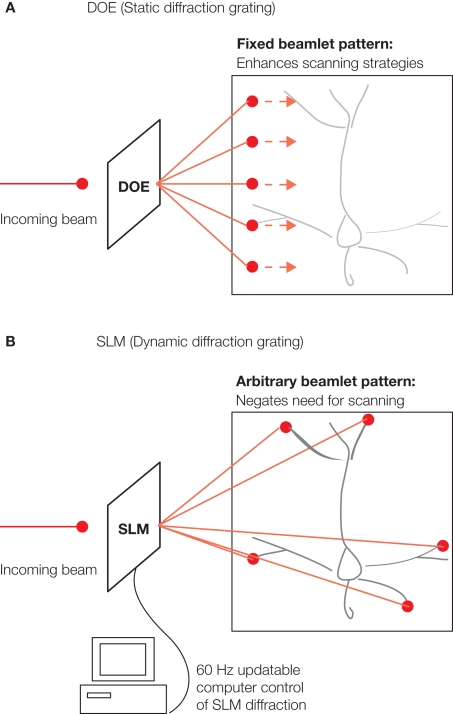
Two-photon microscopy is often performed at slow frame rates due to the need to serially scan all points in a field of view with a single laser beam. To overcome this problem, we have developed two optical methods that split and multiplex a laser beam across the sample. In the first method a diffractive optical element (DOE) generates a fixed number of beamlets that are scanned in parallel resulting in a corresponding increase in speed or in signal-to-noise ratio in time-lapse measurements. The second method uses a computer-controlled spatial light modulator (SLM) to generate any arbitrary spatio-temporal light pattern. With an SLM one can image or photostimulate any predefined region of the image such as neurons or dendritic spines. In addition, SLMs can be used to mimic a large number of optical transfer functions including light path corrections as adaptive optics.

Keywords: calcium imaging; diffractive optical element; imaging; spatial light modulator; two-photon microscopy.


Figures

Figure 1
Figure 1
Multibeam two-photon excitation with diffractive optical elements (DOE) or spatial light modulators (SLM). Both the DOE and the SLM use diffraction to create an output pattern of multiple beamlets of light from a single input beam. (A) DOE is a static diffraction grating which creates a single particular output pattern, in this case a linear array of evenly spaced beamlets. These beamlets can be used to increase speed and/or increase sampling of imaging given that they allow for simultaneous exposure of multiple full power excitation points either in parallel or in series over portions of the field. (B) The SLM is dynamically controllable via computer and can create arbitrary patterns of output light to fit the spatial aspects of particular imaging fields (i.e., targeting particular neurites or cells). Furthermore, the SLM can have a new diffraction grating pattern thereby creating a new output pattern of beamlets every 16.7 ms (or even faster depending on type of the used SLM). SLMs allow scanless microscopy for both imaging as well as photostimulation experiments all at multiple spatial points simultaneously.
Figure 2
Figure 2
Diffractive optical element (DOE)-based high-speed imaging. Adapted from Watson et al. (2009). (Ai) schematic of traditional single beam imaging requiring that a single beam scan of all lines to be imaged necessitating a relatively long scan time per frame. (Bi) Multiple beamlets created by the DOE (each as powerful as the single beamlet used for single beam imaging) simultaneously sweep the field with each beamlet covering a small portion of the territory to quickly excite the entire field of view. (Aii) Image created by scanning across a population of calcium indicator-loaded cells (Fura 2-AM) using single beam scanning and photomultiplier tube detection. Scanning at this resolution and mirror sweep speed was 1 Hz at the fastest. (Bii) DOE 10 Hz scanning of same field of with 11 beamlets and with light gathering using a CCD camera at the same mirror sweep speed. (Aiii) Calcium indicator fluorescence recorded with single beam imaging from a patch clamped neuron indicated by arrow in (Aii). Above: calcium indicator fluorescence versus time of the patch clamped neuron. Below: electrophysiological tracing recorded simultaneously from the same cell as was being imaged, demonstrating periods of induced action potential generation. The first three action potential bursts have two action potentials per burst and are undetectable in the calcium indicator brightness trace, the later bursts have three action potentials each give somewhat clearer signals in the calcium indicator tracing. (Biii) Imaging of calcium transients at 10 Hz using DOE imaging. Bursts of either two or three action potentials are easily detectible in this higher speed scheme, likely due increased sampling rate. All imaging at 800-nm light with detection at 510 nm.
Figure 3
Figure 3
Spatial light modulator (SLM) two-photon imaging and photostimulation. (Ai) Arbitrary pattern of desired output from SLM in the shape of letters “HHMI”. (Aii) Pattern by SLM from a single circular input beam, projected through 60× 0.9NA objective into agar block filled with Alexa 488 fluorescent dye. (Bi) Similar to (Ai), however more complex desired output pattern of output from SLM in the shape of a patch clamped neuron. This image was thresholded and binarized to create a final output template. (Bii) SLM-created pattern projected into Alexa 488-filled agar block under 40× 0.8NA objective. (Ci) Basal dendrite from a layer 5 pyramidal neuron in an acute slice of mouse neocortex. The neuron is loaded with Alexa-488 and the slice bathed in MNI-glutamate. The SLM was used to create a diffraction pattern placing beamlets adjacent to individual spines of the dendrite (red dots). Pulses of excitation light delivered simultaneously at these points using the SLM triggered uncaging of MNI-glutmate. (Cii) Whole cell patch clamp recording at cellular soma of integrated potentials created by simultaneous uncaging at the spots indicated. Each horizontal trace represents a repetition of the stimulation and reveals the uncaging potentials recorded at the soma. (Di) Similar to (C), however now in a new neuron with uncaging targeted to locations near a dendritic shaft rather than near spines. (Dii) Patch clamp recordings of multiple trials of multi-point simultaneous uncaging revealing the uncaging potentials recorded at the soma. See Nikolenko et al. (2008) for more detailed description of the methods used for these recordings.

References

    1. Araya R., Eisenthal K. B., Yuste R. (2006). Dendritic spines linearize the summation of excitatory potentials. Proc. Natl. Acad. Sci. USA 103, 18779–1880410.1073/pnas.0609225103 - DOI - PMC - PubMed
    1. Denk W. (1994). Two-photon scanning photochemical microscopy: mapping ligand-gated ion channel distributions. Proc. Natl. Acad. Sci. USA 91, 6629–663310.1073/pnas.91.14.6629 - DOI - PMC - PubMed
    1. Denk W., Delaney K. R., Gelperin A., Kleinfeld D., Strowbridge B. W., Tank D. W., Yuste R. (1994). Anatomical and functional imaging of neurons using 2-photon laser scanning microscopy. J. Neurosci. Meth. 54, 151–16210.1016/0165-0270(94)90189-9 - DOI - PubMed
    1. Denk W., Strickler J. H., Webb W. W. (1990). Two-photon laser scanning fluorescence microscopy. Science 248, 73–7610.1126/science.2321027 - DOI - PubMed
    1. Egger M., Petran M. (1967). New reflected-light microscope for viewing unstained brain and ganglion cells Science 157, 305–30710.1126/science.157.3786.305 - DOI - PubMed

LinkOut - more resources