

A novel solid-angle tomosynthesis (SAT) scanning scheme
- PMID: 20879579
- PMCID: PMC2921422
- DOI: 10.1118/1.3460341
A novel solid-angle tomosynthesis (SAT) scanning scheme
Abstract
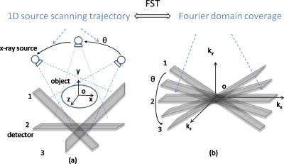
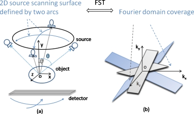
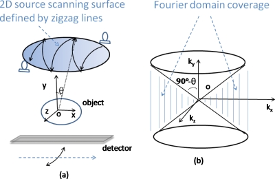
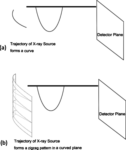
Purpose: Digital tomosynthesis (DTS) recently gained extensive research interests in both diagnostic and radiation therapy fields. Conventional DTS images are generated by scanning an x-ray source and flat-panel detector pair on opposite sides of an object, with the scanning trajectory on a one-dimensional curve. A novel tomosynthesis method named solid-angle tomosynthesis (SAT) is proposed, where the x-ray source scans on an arbitrary shaped two-dimensional surface.
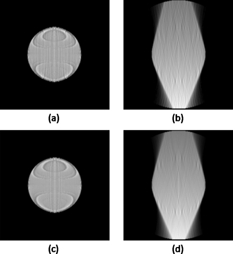
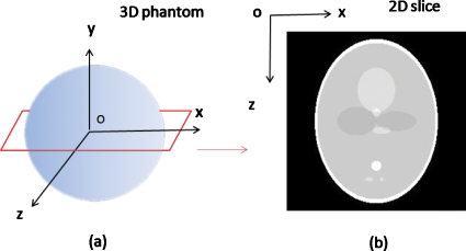
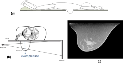
Methods: An iterative algorithm in the form of total variation regulated expectation maximization is developed for SAT image reconstruction. The feasibility and effectiveness of SAT is corroborated by computer simulation studies using three-dimensional (3D) numerical phantoms including a 3D Shepp-Logan phantom and a volumetric CT image set of a human breast.
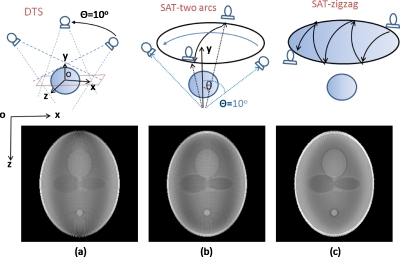
Results: SAT is able to cover more space in Fourier domain more uniformly than conventional DTS. Greater coverage and more isotropy in the frequency domain translate to fewer artifacts and more accurately restored features in the in-plane reconstruction.
Conclusions: Comparing with conventional DTS, SAT allows cone-shaped x-ray beams to project from more solid angles, thus provides more coverage in the spatial-frequency domain, resulting in better quality of reconstructed image.
Figures
Similar articles
-
Quantifying the tibiofemoral joint space using x-ray tomosynthesis.Med Phys. 2011 Dec;38(12):6672-82. doi: 10.1118/1.3662891. Med Phys. 2011. PMID: 22149849
-
A three-dimensional-weighted cone beam filtered backprojection (CB-FBP) algorithm for image reconstruction in volumetric CT-helical scanning.Phys Med Biol. 2006 Feb 21;51(4):855-74. doi: 10.1088/0031-9155/51/4/007. Epub 2006 Jan 25. Phys Med Biol. 2006. PMID: 16467583
-
Implementation and evaluation of an expectation maximization reconstruction algorithm for gamma emission breast tomosynthesis.Med Phys. 2012 Dec;39(12):7580-92. doi: 10.1118/1.4764480. Med Phys. 2012. PMID: 23231306 Free PMC article.
-
Digital x-ray tomosynthesis: current state of the art and clinical potential.Phys Med Biol. 2003 Oct 7;48(19):R65-106. doi: 10.1088/0031-9155/48/19/r01. Phys Med Biol. 2003. PMID: 14579853 Review.
-
Evaluation of back projection methods for breast tomosynthesis image reconstruction.J Digit Imaging. 2015 Jun;28(3):338-45. doi: 10.1007/s10278-014-9736-6. J Digit Imaging. 2015. PMID: 25384538 Free PMC article. Review.
Cited by
-
A geometric calibration method for the digital chest tomosynthesis with dual-axis scanning geometry.PLoS One. 2019 Apr 25;14(4):e0216054. doi: 10.1371/journal.pone.0216054. eCollection 2019. PLoS One. 2019. PMID: 31022255 Free PMC article.
-
A review of breast tomosynthesis. Part I. The image acquisition process.Med Phys. 2013 Jan;40(1):014301. doi: 10.1118/1.4770279. Med Phys. 2013. PMID: 23298126 Free PMC article. Review.
References
-
- Niklason L. T. et al., “Digital tomosynthesis in breast imaging,” Radiology RADLAX 205(2), 399–406 (1997). - PubMed
-
- Wu T., Stewart A., Stanton M., McCauley T., Phillips W., Kopans D. B., Moore R. H., Eberhard J. W., Opsahl-Ong B., Niklason L., and Williams M. B., “Tomographic mammography using a limited number of low-dose cone-beam projection images,” Med. Phys. MPHYA6 30(3), 365–380 (2003).10.1118/1.1543934 - DOI - PubMed
MeSH terms
LinkOut - more resources
Full Text Sources
Medical
Research Materials
