. 2010 Oct;32(4):809-17.
doi: 10.1002/jmri.22330.

Diffusion tensor tractography of the human brain cortico-ponto-cerebellar pathways: a quantitative preliminary study

Affiliations

Diffusion tensor tractography of the human brain cortico-ponto-cerebellar pathways: a quantitative preliminary study

Arash Kamali et al. J Magn Reson Imaging. 2010 Oct.

Abstract

Purpose: To investigate the utility of diffusion tensor tractography at 1mm slice thickness to map and quantify the whole trajectory of different cortico-ponto-cerebellar pathways of the healthy adult human brain.

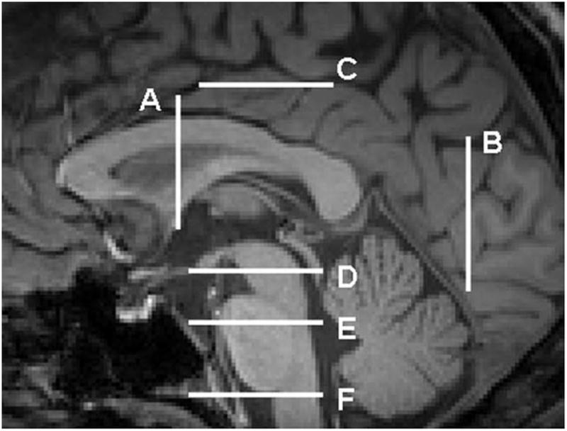
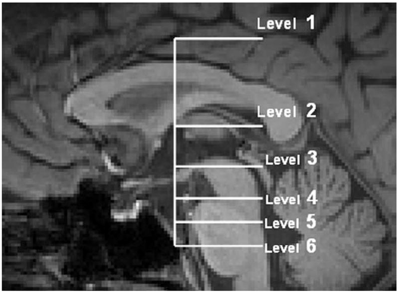
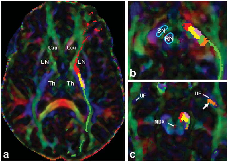
Materials and methods: This work was approved by the local Institutional Review Board, and was Health Insurance Portability and Accountability Act (HIPAA) compliant. Five healthy right-handed men (age range, 24-37 years) were studied and written informed consent was obtained. Diffusion tensor imaging data acquired with 1-mm slice thickness at a 3.0 Tesla (T) clinical MRI scanner were prepared and analyzed using tractography methods to reconstruct the cortico-ponto-cerebellar pathways which included the fronto-ponto-cerebellar, parieto-ponto-cerebellar, occipito-ponto-cerebellar, and temporo-ponto-cerebellar tracts.

Results: We demonstrate the feasibility of tractographic mapping and quantification of the four cortico-ponto-cerebellar system components based on their cortical connections in the healthy human brain using DTI data with thin 1-mm sections.

Conclusion: In vivo quantification of different cortico-ponto-cerebellar pathways based on cortical connection is feasible, using 1-mm slices at 3.0T.


Figures

Figure 1
Figure 1
ROI locations (ROI 1 and 2) used for reconstructions of the four cortico-ponto-cerebellar and corticospinal tracts. a: Fronto-ponto-cerebellar tract. b: Parieto-ponto-cerebellar tract. c: Occipito-ponto-cerebellar tract. d: Temporo-ponto-cerebellar tract. e: Corticospinal tract. The ROIs are depicted by shapes outlined in pink, which yielded a tract reconstruction in yellow color on a DTI principal vector coded map (red = right–left; green = anterior–posterior; blue = superior–inferior). In a, the ROI 1 was placed on the whole lateral segment of the crus cerebri at the lowest axial level in which the red nuclei are visible on the T2-weighted map (level D in Fig. 2) and ROI 2 was seeded on the fibers generated in the whole anterior limb of internal capsule (level A in Fig. 2). In b, ROI 1 was used on the cortical areas posterior to the precentral sulcus and anterior to the parieto-occipital sulcus (level C in Fig. 2), and ROI 2 was placed on the fibers generated in the lateral portion of the crus cerebri at the level D in Figure 2. A not operation was also done to remove part of the CST whichmay have been included with the PPC. In c, ROI 1 was used on the posterior one-third portion (dorso-lateral portion) of the cerebral peduncle (level D in Fig. 2) and ROI 2 was selected on the fibers generated in the occipital cortex at the axial level which is passing through the posteriormost of the cerebellum (level B in Fig. 2). A not operation was also done to remove part of the CST which might have been included with the OPC. In d, ROI 1 was seeded on the posterior one-third portion (dorso-lateral portion) of the cerebral peduncle (the same as ROI1 in Fig. 1c) and ROI 2 was placed at the same axial level on the fibers generated posterior to the uncinate fasciculus. In e, ROI locations (ROI 1 and 2 and 3) used for reconstruction of corticospinal tract. ROI 1 was located on the entire upper Medulla Oblongata (level F in Fig. 2), The second ROI was seeded on the basis pontis (level E in Fig. 2), and the third ROI was placed on the trajectories generated in the primary motor cortex ventral to the central sulcus. Anatomical landmarks are labeled as follows: AC = anterior commissure; UF = uncinate fasciculus. [Color figure can be viewed in the online issue, which is available at wileyonlinelibrary.com.]
Figure 2
Figure 2
Structural (T1-weighted) MRI of the sagittal midline plane showing the different coronal and axial sections which was used for ROI placement in Figure 1. A: The coronal slice in which anterior commissure is visible. B: The coronal slice which passes through the most posterior portion of the cerebellum in the midsagittal slice. C: The axial level corresponding to the cingulate sulcus in the midsagittal cut. D: The lowest axial level in which the red nuclei are visible on the T2-weighted map. E: The intersection of superior and middle one-third portions of the pons. F: The axial level passing through the upper medulla oblongata.
Figure 3
Figure 3
The reconstructed tracts, overlaid on a 3D T1- weighted lateral (left images) and postero-lateral view (right images). a: Fronto-ponto-cerebellar tract. b: Parieto-pontocerebellar tract. Blue fibers are originating from the more anterior portions of the parietal cortex and cross at upper axial levels of the pons in comparison to yellow fibers which are originating from the more posterior parietal cortex and cross in lower pontine levels. c: Occipito-ponto-cerebellar tract. d: Temporo-ponto-cerebellar tract.
Figure 4
Figure 4
Structural (T1-weighted) MRI of the sagittal midline plane showing the different axial sections of the brain which CPC pathways are mapped in the following images. Telencephalon (level 1) at the axial level corresponding to the cingulate sulcus. Diencephalon (level 2) at the axial level which the maximum length of putamen is visible. Mesencephalon (level 3) at mesencephalo-diencephalic level which corresponds to the axial level that is passing through the superior margin of mamillary body on midsagittal plane. Mesencephalon (level 4) at the lowest mesencephalon. Pons (levels 5, 6) at the intersection of superior and middle one third (level 5) and middle and inferior one-third (level 6) portions of the pons at the midsagittal plane.
Figure 5
Figure 5
Transverse DTI color-coded map and concordant T2-weighted MR images for mapping the fronto-ponto-cerebellar (red), parieto-ponto-cerebellar (yellow), occipito-ponto-cerebellar (Green), temporo-ponto-cerebellar (orange), and corticospinal tract (pink). a: View at the axial level corresponding to the cingulate sulcus (Corresponds to the level 1 in Fig. 4). b: View at the diencephalon at the axial level which the most length of putamen is visible (corresponds to the level 2 in Fig. 4). The white arrow shows the prefrontal cortical connections of FP tract (c) view at the mesencephalo-diencephalic level (Corresponds to the level 3 in Fig. 4). The lateral portion of orange fibers are the ascending part of temporo-pontine tract which turns to the descending branch at this level and descend in dorsal cerebral peduncle (the medial portion of orange fibers). Well delineated anatomic landmarks are labeled as follows: CST = Corticospinal tract; LN = lentiform nucleus; RN = red nucleus; SN = substantia nigra; Th = thalamus; V = vermis of cerebellum. [Color figure can be viewed in the online issue, which is available at wileyonlinelibrary.com.]
Figure 6
Figure 6
Transverse principal eignvector modulated by FA map fused with the corresponding T2-weighted MR images to illustrate the fronto-ponto-cerebellar (red), parieto-ponto-cerebellar (yellow), occipito-ponto-cerebellar (green), temporo-pontocerebellar (orange), and corticospinal tract (pink) in multiple axial cuts along the long axis of the brainstem indicated in Figure 4. a: View at the axial level of mesencephalic decussation (central red area on DTI color-coded map) at lowest mesencephalon (corresponds to the level 4 in Fig. 4). The white arrow is pointing at the ascending fibers of TPC which are originating from anterior temporal lobe and ascending ventrally to the temporal horn of lateral ventricle (THLV) and dorsally to the uncinate fasciculus fibers. b: View at the axial level of the intersection of superior and middle one-third portions of the pons in the midsagittal plane (corresponds to the level 5 in Fig. 4). c: View at the axial level of the intersection of middle and inferior one-third portions of the pons in the midsagittal plane (corresponds to the level 6 in Fig. 4). Well delineated anatomic landmarks are labeled as follows: Cing = Cingulum (inferior horn); DN = dentate nucleus; DTF = dorsal transverse fibers; ICP = inferior cerebellar peduncle; IV = fourth ventricle; MDX = mesencephalic decussation; MCP = middle cerebellar peduncle; SCP = superior cerebellar peduncle; THLV = temporal horn of lateral ventricle; VTF = ventral transverse fibers; V = vermis of cerebellum; UF = uncinate fasciculus. [Color figure can be viewed in the online issue, which is available at wiley onlinelibrary.com.]
Figure 7
Figure 7
Transverse DTI color-coded map images for mapping the fronto-ponto-cerebellar (red), parieto-ponto-cerebellar (yellow), occipito-ponto-cerebellar (green), temporo-ponto-cerebellar (orange), and the corticospinal tract (pink) in one of the subjects which the CST is passing from the lateral side of the parieto-ponto-cerebellar tract. a: View at the diencephalon at the axial level which the most length of putamen is visible (corresponds to the level 2 in Fig. 4). b: View at the mesencephalodiencephalic level (Corresponds to the level 3 in Fig. 4). c: View at the axial level of mesencephalic decussation (MDX) at lowest mesencephalon (corresponds to the level 4 in Fig. 4). The white arrow is pointing at the ascending fibers of the TPC which are passing dorsally to the uncinate fasciculus (UF) fibers. Well delineated anatomic landmarks are labeled as follows: LN = lentiform nucleus; MDX = mesencephalic decussation; RN = red nucleus; SN = substantia nigra; Th = thalamus; UF = uncinate fasciculus. [Color figure can be viewed in the online issue, which is available at wileyonlinelibrary.com.]

Similar articles

Cited by

References

    1. Afifi AK, Bergman RA. Text and atlas. New York: McGraw-Hill; 1998. Functional neuroanatomy; p. 730.
    1. Nolte J. An introduction to its functional anatomy. 5. St. Louis: MO: Mosby; 2002. The human brain; p. 650.
    1. Kitamura K, Nakayama K, Kosaka S, et al. Diffusion tensor imaging of the cortico-ponto-cerebellar pathway in patients with adult-onset ataxic neurodegenerative disease. Neuroradiology. 2008;50:285–292. - PubMed
    1. Adachi M, Hosoya T, Yamaguchi K, et al. Diffusion- and T2- weighted MRI of the transverse pontine fibers in spinocerebellar degeneration. Neuroradiology. 2000;42:803–809. - PubMed
    1. Blain CR, Barker GJ, Jarosz JM, et al. Measuring brain stem and cerebellar damage in parkinsonian syndromes using diffusion tensor MRI. Neurology. 2006;67:2199–2205. - PubMed

Publication types