

Review
doi: 10.1101/cshperspect.a000299.
Epub 2010 Oct 6.
Bacterial nanomachines: the flagellum and type III injectisome
Affiliations
- PMID: 20926516
- PMCID: PMC2964186
- DOI: 10.1101/cshperspect.a000299
Item in Clipboard
Review
Bacterial nanomachines: the flagellum and type III injectisome
Cold Spring Harb Perspect Biol.
2010 Nov.
Abstract
The bacterial flagellum and the virulence-associated injectisome are complex, structurally related nanomachines that bacteria use for locomotion or the translocation of virulence factors into eukaryotic host cells. The assembly of both structures and the transfer of extracellular proteins is mediated by a unique, multicomponent transport apparatus, the type III secretion system. Here, we discuss the significant progress that has been made in recent years in the visualization and functional characterization of many components of the type III secretion system, the structure of the bacterial flagellum, and the injectisome complex.
Figures
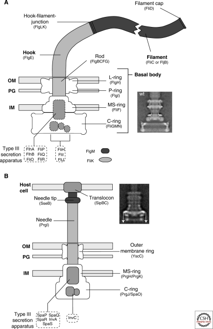
Schematic comparison of the flagellum and type III injectisome of Salmonella. (A) Schematic overview of the flagellum of Salmonella. The structure of the flagellum consists of three parts: 1) a basal body with a flagellar-specific type III secretion system within the inner membrane ring; 2) a flexible hook acting as a universal joint to 3) the rigid filament. Dashed boxes illustrate proteins with functions in flagellar type III secretion. Also indicated are FlgM, the negative regulator of late substrate gene expression that is secreted after hook-basal-body secretion, and the hook-length regulator FliK that measures rod-hook length and ultimately determines the secretion substrate specificity switch. OM = outer membrane; PG = peptidoglycan; IM = inner membrane. The inlay EM (electron micrograph) picture shows an isolated hook-basal-body complex of Salmonella (Thomas et al. 2001). (B) Schematic overview of the SPI-1 injectisome of Salmonella. Many components of the flagellum and injectisome are structurally and/or functionally related. The injectisome structure can also be divided into three main parts: 1) the basal body with the type III secretion apparatus within the inner membrane ring; 2) a straight needle connecting the bacterial secretion system to 3) the translocon complex that forms a pore in the membrane of eukaryotic host cells. The inlay EM picture shows an injectisome of Salmonella enterica (Marlovits et al. 2004). (The arrows on this image served in the original paper to explain aspects of the reconstruction procedure.) (A [inlay], Reprinted, with permission, from Thomas et al. 2001 [© ASM]; B [inlay] reprinted, with permission, from Marlovits et al. 2004 [© AAAS].)
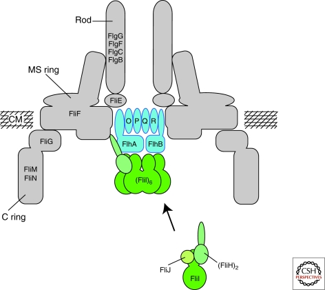
Schematic of the flagellar type III secretion apparatus. FlhA, FlhB, FliO, FliP, FliQ, and FliR are integral membrane components of the flagellar type III secretion apparatus. The membrane components of the T3S apparatus are believed to assemble within a central pore of the MS-ring. FliI, the flagellar-specific ATPase, FliH, the regulator of FliI and FliJ, a general chaperone, are soluble proteins. FliI forms a heterotrimer together with the homodimer FliH in the cytoplasm. After docking to the membrane components of the T3S apparatus, FliI forms a functional hexamer. The protein translocation is dependent on the proton motive force and the substrates have to be secreted in an unfolded state through a narrow channel of about 2.0 nm in diameter. It has been proposed that FliI facilitates substrate unfolding in an ATP-dependent manner. CM = cytoplasmic membrane. (Reprinted, with permission, from Minamino et al. 2008a [Royal Society of Chemistry].)
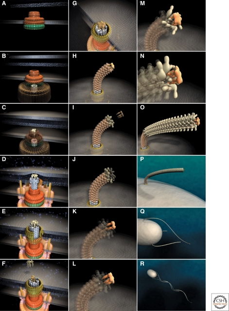
Steps in assembly of the bacterial flagellum. The self-assembly process of the bacterial flagellum starts from the top left (A) and proceeds to the bottom right (R). Assembly starts with the formation of the MS-ring in the cytoplasmic membrane (A). Afterward, the cytoplasmic C-ring is attached to the MS-ring and the flagellar-specific type III secretion apparatus assembles within a central pore of the MS-ring (B). Flagellar secretion substrates are now secreted specifically via the T3S apparatus. Flagellar proteins that reach the distal end of the growing structure, self-assemble onto the existing structure with the help of distal cap proteins (shown as pentamers at the tips of the axial structures) (C–O). First, the rod acting as a driveshaft is assembled beneath the rod-cap, which is also a muramidase to allow penetration through the peptidoglycan layer (D). In addition, motor force generators that couple proton flow to torque generation assemble in the cytoplasmic membrane and interact with C-ring components (D). Rod assembly ends with the formation of the PL-ring bushing, outer membrane penetration, and the replacement of the rod scaffold with the hook scaffold (E–G). Afterward, hook subunits are secreted and the hook grows to a final length of 55 nm (Hirano et al. 1994), triggering a secretion specificity switch from rod-hook-type substrates to late-secretion substrates (H). Upon completion of the hook-basal-body complex, hook-filament junction proteins (I–J), the filament cap (K–L), and filament subunits are secreted, and the filament grows to a maximal length of about 10–15 µM (M–R). (Reprinted, with permission, from Minamino et al. 2008a [Royal Society of Chemistry].)
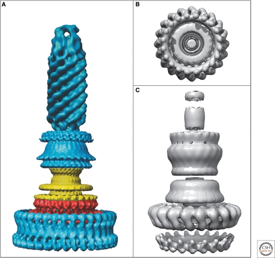
EM reconstructions of basal bodies of the flagellum and type III injectisome of Salmonella. (A) Model of the bacterial hook-basal-body complex based on EM reconstructions (Derosier 2006). (B, C) Surface renderings of the injectisome basal body and needle structure based on EM reconstruction data EmDep Database accession number EMD1100 (Marlovits et al. 2004). (B) View of the injectisome basal body complex from the cytoplasm and (C) side-view of the injectisome basal body with attached needle. (A, Reprinted, with permission, from Derosier 2006 [© Elsevier]; B, C, based on Marlovits et al. 2004 [© AAAS].)
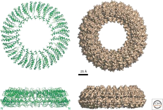
Model of the injectisome inner membrane ring, EscJ. Shown are ribbon and surface representations of the 24-subunit EscJ ring model. The sideview illustrates the two-layered exterior structure that closely resembles the flagellar MS-ring structure based on cryo-EM studies. The N-termini of the EscJ subunits are located at the wide face of the ring (also labeled N in the ribbon diagrams sideview). Scale bar 25 Å. (Reprinted, with permission, from Yip et al. 2005 [Nature Publishing Group].)
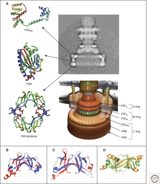
Crystal structures of the components of the C-ring, FliGMC, FliM, and FliN. (A) Left panel: Ribbon representation of the crystal structures of FliGMC (middle and C-terminal domains of FliG), FliM, and the doughnut-like tetramer of FliN. Upper right panel: cyro-EM image of a hook-basal-body complex. The arrows illustrate the positions of the FliG, FliM, and FliN proteins in the C-ring structure. Lower right panel: Model of the flagellar basal body complex with proposed locations of FliF, FliG, FliM, and FliN forming the MS-ring and C-ring, respectively (Minamino et al. 2008b). (B,C) Comparison of the homologous structures of FliN and HrcQBC (Fadouloglou et al. 2004). (B) Crystal structure of the C-terminal fragment of FliN of Thermotoga maritima (PDB 1O6A). (C) Crystal structure of the C-terminal domain of HrcQBC of Pseudomonas syringae (PDB 1O9Y) (Fadouloglou et al. 2004). (D) Ribbon representation of the FliN dimer (gold) superimposed on half of the HrcQBC tetramer (green) illustrating the highly homologous structure (Brown et al. 2005). (A, reprinted, with permission, from Minamino et al. 2008b [© Elsevier]; B, Protein data base accession number 1O6A, based on Fadouloglou et al. 2004; C, Protein data base accession number 1O9Y, based on Fadouloglou et al. 2004; D, reprinted, with permission, from Brown et al. 2005 [© ASM].)
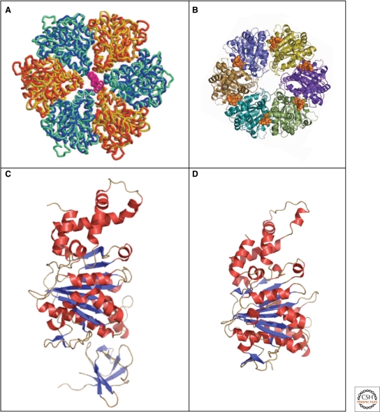
Crystal structures of the type III secretion ATPases, FliI, and EscN. (A) Model of the ATPase domain of the FliI hexamer (blue and yellow) superimposed onto the ATPase domain (blue-green) and (orange) of F1-ATPase (Imada et al. 2007). (B) Top-view of the EscN hexamer model; position of the ATP shown in a van-der-Waals representation in gold (Zarivach et al. 2007). (C) Crystal structure of the flagellar type III ATPase FliI (Δ1–18) missing the first 18 residues (PDB 2DPY). (D) Crystal structure of the C-terminal domain, residues 103–446 of the injectisome ATPase EscN (PDB 2OBL). (A, reprinted, with permission, from Imada et al. 2007 [© National Academy of Sciences]; B, reprinted, with permission, from Zarivach et al. 2007 [Nature Publishing Group]; C, Protein database accession number 2DPY, based on Imada et al. 2007; D, Protein database accession number 2OBL, based on Zarivach et al. 2007.)
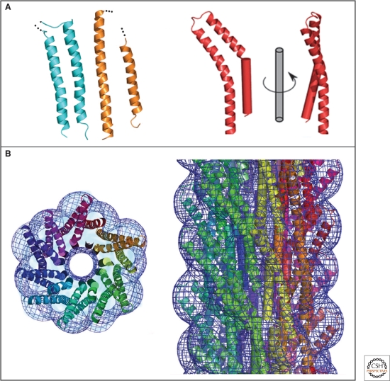
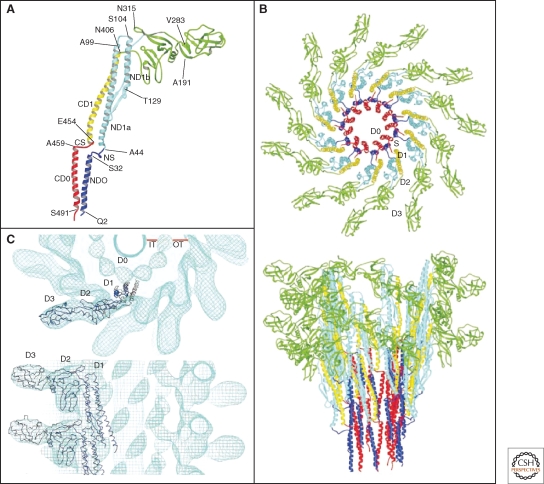
Crystal structure and molecular model of a type III secretion needle. (A) Ribbon representation of the D0 domain of flagellin (cyan), the ordered (chaperone-bound) region of EspA (orange) and molecule A of MxiH (red). The modeled N-terminal helix of MxiH is also shown rotated by 90° about the long axis of the molecule. (B) Model of the type III secretion needle obtained by docking of the atomic model of MxiH into the EM density of the Shigella T3SS needle. Left panel: end-on view of a 40-Å-thick section of the assembled needle. Each MxiH monomer is colored differently. The EM density is shown as a blue mesh. Right panel: side-view of the assembled needle, with colors as in the left panel. Note that the needle models in the left and right panel are not shown at the same scale. (Reprinted, with permission, from Deane et al. 2006 [© National Academy of Sciences].)
Model of the supercoiled flagellar hook and crystal structure of the hook subunit fragment, FlgE31. (A) Docking of the atomic model of the crystal structure of the hook subunit fragment FlgE31 into the outer two domains of the hook obtained by cyro-EM. Left panel: end-on-view; right panel: side-view. The hook EM density is shown as a purple mesh. (B) Atomic model of the supercoiled hook and a schematic diagram of the basal body complex. OM, outer membrane; PG, peptidoglycan layer; CM, cytoplasmic membrane. (C) Magnified, atomic model of the supercoiled hook shown in (B). The innermost and the outermost protofilaments are displayed on the left and right, respectively. Dotted gray lines represent the central channel. (Reprinted, with permission, from Samatey et al. 2004 [Nature Publishing Group].)
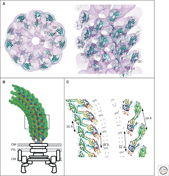
Crystal structure and model of the flagellar filament. (A) Atomic model of the flagellar filament obtained by cyro-EM. Ribbon representation of the filament subunit (Yonekura et al. 2003). (B) Ribbon representation of the model of the flagellar filament. Upper panel: end-on-view from the distal end of the filament displaying 11 subunits. Lower panel: side-view from outside of the filament (Yonekura et al. 2003). (C) Docking of a protofilament into the electron density map of the filament. Upper panel: end-on-view from the top. Bottom panel: Side-view. D0, D1, D2, and D3 indicate domains of the flagellin protein (Samatey et al. 2001). (A, B, Reprinted, with permission, from Yonekura et al. 2003; C, reprinted, with permission, from Samatey et al. 2001 [all Nature Publishing Group].)
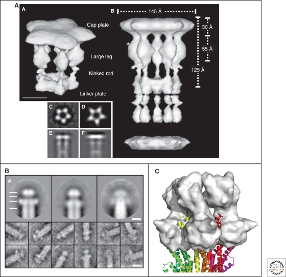
EM images of the flagellar filament cap, needle tip and model of the needle-tip interaction. (A) 3D-EM image reconstruction of the flagellar cap pentamer (labeled A in the image) and decamer (labeled B in the image). On the lower left side of the image are shown: averaged end-on-view (labeled C); projection of the 3D reconstruction along the 5-fold axis (labeled D); averaged side-view (labeled E), and projection of the 3D reconstruction perpendicular to the 5-fold axis (labeled F) (Maki-Yonekura et al. 2000). (B) Upper three panels: averaged EM images of the needle tip complexes formed by LcrV (left; resolution 1.5 nm), PcrV (center; resolution 1.5 nm), and AcrV (right; resolution 2.5 nm). Also visible is the central channel of both the needle and tip complex. Lower images on the bottom display typical single images (Mueller et al. 2005). (C) The LcrV tip complex modeled onto the distal end of a injectisome needle. The LcrV tip complex is displayed in surface representation (gray) (Deane et al. 2006). (A, Reprinted, with permission, from Maki-Yonekura et al. 2003 [© National Academy of Sciences]; B, reprinted, with permission, from Mueller et al. 2005 [© AAAS]; C, reprinted, with permission, from Deane et al. 2006 [© National Academy of Sciences].)
References
-
- Aizawa SI 1996. Flagellar assembly in Salmonella typhimurium. Mol Microbiol 19: 1–5 - PubMed
-
- Akeda Y, Galán JE 2005. Chaperone release and unfolding of substrates in type III secretion. Nature 437: 911–915 - PubMed
-
- Asakura S 1970. Polymerization of flagellin and polymorphism of flagella. Adv Biophys 1: 99–155 - PubMed
-
- Berg HC, Anderson RA 1973. Bacteria swim by rotating their flagellar filaments. Nature 245: 380–382 - PubMed
-
- Berg H 2003. The rotary motor of bacterial flagella. Annu Rev Biochem 72: 19–54 - PubMed
Publication types
MeSH terms
Substances
Grants and funding
LinkOut - more resources
Full Text Sources
Other Literature Sources