. 2011 Jan 7;286(1):234-42.
doi: 10.1074/jbc.M110.187211. Epub 2010 Oct 20.

Molecular rearrangements involved in the capsid shell maturation of bacteriophage T7

Affiliations

Molecular rearrangements involved in the capsid shell maturation of bacteriophage T7

Alina Ionel et al. J Biol Chem. .

Abstract

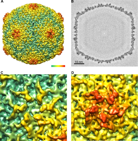
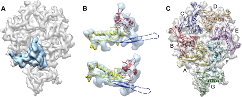
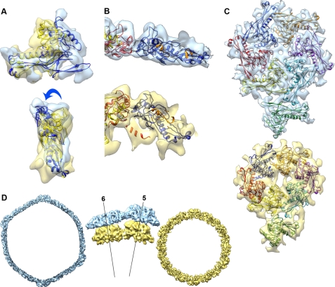
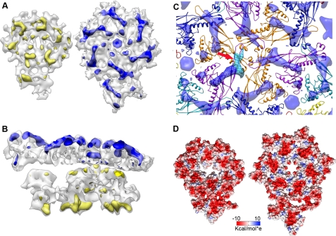
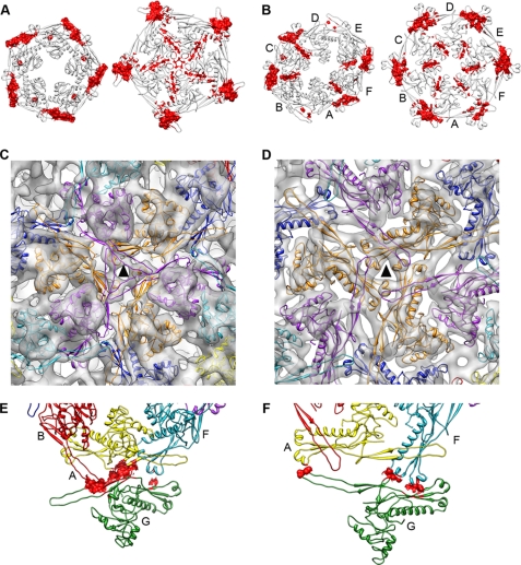
Maturation of dsDNA bacteriophages involves assembling the virus prohead from a limited set of structural components followed by rearrangements required for the stability that is necessary for infecting a host under challenging environmental conditions. Here, we determine the mature capsid structure of T7 at 1 nm resolution by cryo-electron microscopy and compare it with the prohead to reveal the molecular basis of T7 shell maturation. The mature capsid presents an expanded and thinner shell, with a drastic rearrangement of the major protein monomers that increases in their interacting surfaces, in turn resulting in a new bonding lattice. The rearrangements include tilting, in-plane rotation, and radial expansion of the subunits, as well as a relative bending of the A- and P-domains of each subunit. The unique features of this shell transformation, which does not employ the accessory proteins, inserted domains, or molecular interactions observed in other phages, suggest a simple capsid assembling strategy that may have appeared early in the evolution of these viruses.


Figures

FIGURE 1.
FIGURE 1.
Three-dimensional reconstruction of the mature capsid. A, surface rendering viewed along a 2-fold axis of icosahedral symmetry. Numbers indicate the 5-fold, 3-fold, and 2-fold icosahedral symmetry axes. The color-coded bar represents depth measurement. B, central section through the density map. Bar represents 10 nm. C, close-up view of the hexamer. D, close-up view of the pentamer. The density is contoured at 3σ above the mean.
FIGURE 2.
FIGURE 2.
Segmentation of the asymmetric unit and model of the shell protein gp10A. A, one gp10A monomer subunit is shown in blue within the asymmetric unit in gray. B, gp10A model fitted in the averaged density of the hexameric monomers. Top, outer side view; bottom, perspective view. The ribbon model is colored for the different motifs: A-domain, red; P-domain, yellow; and E-loop, blue. Part of the E-loop (dashed line) is omitted as no hints for the corresponding densities are defined in the average density. C, a pseudo-atomic model of the asymmetric unit of the mature head. The unit contains an entire hexamer (subunits A–F) and one pentamer subunit (subunit G). The color code of the monomers in this figure is maintained throughout the entire report.
FIGURE 3.
FIGURE 3.
Structural changes involved in the T7 shell maturation. A, superposition of models of gp10A for the prohead (yellow) and head (blue) obtained by alignment of the P-domain, showing the bending of the A-domain relative to the P-domain. B, detail of the head (top) and prohead (bottom) hexameric subunits shown tangential to the capsid surface. C, head (top) and prohead (bottom) asymmetric units shown from the outside of the capsid. D, cross-section view of the head (blue) and prohead (yellow) densities. The central detailed side views are shown tangential to the capsid surface, revealing the radial outward movement of the capsomers. The labeled lines represent radial axes along the center of the pentamer (5) and the hexamer (6).
FIGURE 4.
FIGURE 4.
Differences between prohead and mature head capsids. A, left, difference map (yellow) between the experimental and modeled densities for the asymmetric unit of the prohead, as seen from the inner side of the shell. Right, difference map (blue) for the asymmetric unit of the mature head, as seen from the outside of the shell. The difference maps are rendered at 5σ. B, side view of the difference maps. C, difference map around a 3-fold axis involving three identical copies of monomer D (Fig. 2). The volume attributed to the N-terminal domain is colored in dark blue, and the E-loop is in light blue (red arrow). D, electrostatic potential in the surface of the asymmetric unit, as seen from the inside of the virion. Left, prohead. Right, mature head. Negative charge is in red, and positive is in blue.
FIGURE 5.
FIGURE 5.
Changes in the interactions during the maturation of the T7 shell. In all cases, the figures on the left are for the prohead, and the mature head is on the right. A, contact surfaces for the pentamer (red). The view is from the outside of the capsid. B, contact surfaces for the hexamer (red). C and D, interactions around the 3-fold axis (triangle) in the prohead (C) and mature head (D). E and F, residues involved in pentameric-hexameric interactions (red) in the prohead (E) and mature head (F).

References

    1. Fauquet C. M., Mayo M. A., Maniloff J., Desselberger U., Ball L. A. (eds) (2005) Virus Taxonomy: Eighth Report of the International Committee on Taxonomy of Viruses, Elsevier Academic Press, San Diego
    1. Casjens S., Chiu W., Burnett R. M., Garcea R. L. (1997) in Structural Biology of Viruses, pp. 38–79, Oxford University Press, New York
    1. Valpuesta J. M., Carrascosa J. L. (1994) Q. Rev. Biophys. 27, 107–155 - PubMed
    1. Fokine A., Leiman P. G., Shneider M. M., Ahvazi B., Boeshans K. M., Steven A. C., Black L. W., Mesyanzhinov V. V., Rossmann M. G. (2005) Proc. Natl. Acad. Sci. U.S.A. 102, 7163–7168 - PMC - PubMed
    1. Steven A. C., Heymann J. B., Cheng N., Trus B. L., Conway J. F. (2005) Curr. Opin. Struct. Biol. 15, 227–236 - PMC - PubMed

Publication types

Substances

LinkOut - more resources