. 2011 Jan;32(1):137-44.
doi: 10.3174/ajnr.A2239. Epub 2010 Oct 21.

Contrast-enhanced angiographic cone-beam CT of cerebrovascular stents: experimental optimization and clinical application

Affiliations

Contrast-enhanced angiographic cone-beam CT of cerebrovascular stents: experimental optimization and clinical application

N V Patel et al. AJNR Am J Neuroradiol. 2011 Jan.

Abstract

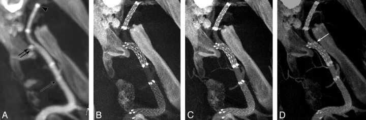
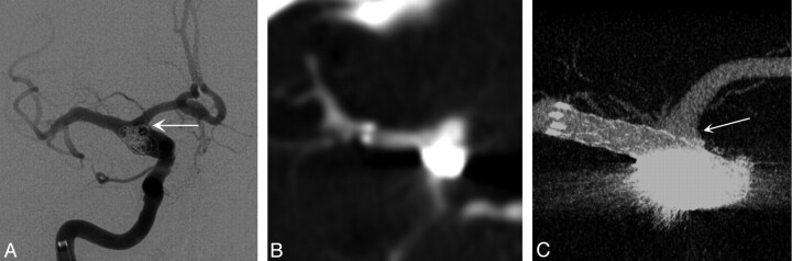
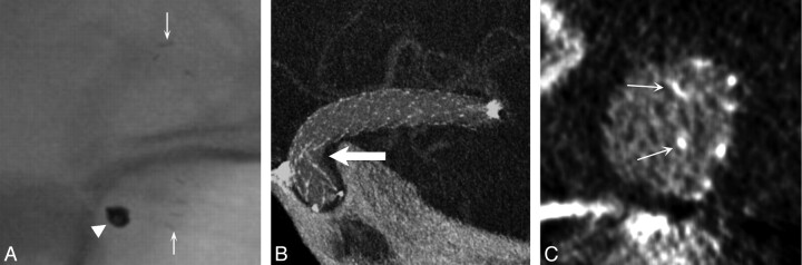
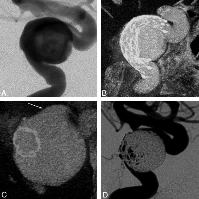
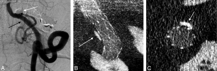
Background and purpose: With modern imaging techniques, visualization of neurovascular stents remains challenging. We present a method for contrast-enhanced C-arm CBCT that provides detailed and simultaneous visualization of neurovascular stents and host arteries.

Materials and methods: CBCT was performed with a rotational angiography system by acquiring 620 projection frames over a 200° arc at 80 kVp and a total of 260 mAs. A superselective intra-arterial contrast injection protocol was optimized in swine experiments and implemented in 57 clinical examinations. High-resolution 3D reconstructions were evaluated by 3 blinded interventional neuroradiologists. Reviewers rated the images by answering questions related to both the quality of the stent and artery visualization and the clinical utility of the images. Raw agreement statistics, ICC, and κ statistics were computed for the questionnaire results.

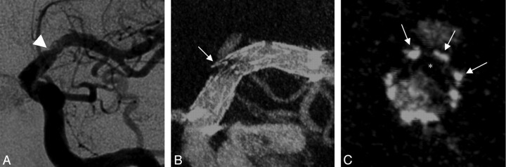
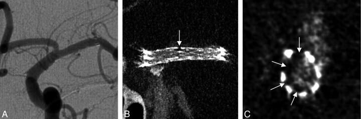
Results: Of 57 clinical evaluations, 5 were not evaluated due to the use of large balloon-mounted stents (n = 4) and a failed contrast injection (n = 1). In 50 of 52 evaluated examinations, the reviewers agreed that simultaneous stent and vessel visualization was of diagnostic quality. There was strong agreement that stent-vessel wall apposition could be assessed (κ = 0.79). CBCT detected contrast filling defects (κ = 0.85) and vascular calcification (κ = 0.68). Artifacts resulting from the aneurysm coil mass impaired the delineation of adjacent structures (κ = 0.72).

Conclusions: We have developed a technique that enables simultaneous clinically useful imaging of neurovascular stents and their host arteries that is unobtainable with other current imaging modalities. Further improvements are required to reduce artifacts from large coil masses due to x-ray scattering.


Figures

Fig 1.
Fig 1.
Results from an in vivo experiment in the swine model, submental projections from 3D datasets. A, Standard flat-panel contrast-enhanced 2 × 2 binned CBCT (10-mm MIP) following the deployment of 3 stents in the left internal maxillary artery. The distal markers of the Enterprise stent (arrow), Wingspan stent (double arrow), and the Neuroform stent (arrowhead) are marked. BD, Nonbinned small FOV contrast-enhanced CBCT images for combined stent and vascular visualization are presented at varying contrast concentrations: 10% (B), 20% (C), and 30% (D), all 10-mm MIPs. See “Materials and Methods” for details. Note also the herniation of Wingspan stent struts into the parent artery as it enters a side branch distally (arrow in D).
Fig 2.
Fig 2.
A, Intraprocedural frontal DSA image acquired during stent-assisted coiling of a right ICA dissecting fusiform aneurysm in a 61-year-old woman. Multiple DSA projections (not shown) were unable to define the coil mass position within the aneurysm and exclude material herniation into the A1 (arrow). B, Postprocedural conventional 64-detector MDCT source image with contrast offers no details of the devices or the adjacent vascular structures (0.95-mm source image). C, Contrast-enhanced CBCT (2.5-mm MIP) clearly shows the stent protecting the right A1 (arrow) and the coil mass secured within the aneurysm boundary.
Fig 3.
Fig 3.
A, Intraprocedural left-anterior-oblique DSA image acquired after primary stent placement in an acute ischemic stroke associated with an atherosclerotic lesion in a 43-year-old woman shows a filling defect of the left MCA (arrowhead). B and C, Contrast-enhanced CBCT in the same projection (5.0-mm MIP, B) and a cross-sectional projection (1.0-mm MIP, C) demonstrate that the filling defect is most likely a clot (asterisk) on the stent surface (arrows indicate struts) rather than plaque material deforming the stent extrinsically.
Fig 4.
Fig 4.
A, Left-anterior-oblique DSA image at 16 months after intracranial stent placement for an atherosclerotic stenosis of the left MCA in a 62-year-old woman. B and C, Contrast-enhanced CBCT scans, left-anterior oblique projection (5.0-mm MIP, B) and cross-sectional projection (1.0-mm MIP, C), show a focal and asymmetric neointimal hyperplasia (arrows) and eccentric stent narrowing related to the presence of underlying atherosclerotic plaque, not appreciated on DSA.
Fig 5.
Fig 5.
A, Follow-up unsubtracted x-ray image acquired at 6 months after stent-assisted coiling of a right superior hypophyseal artery aneurysm does not show any stent struts. Arrows show proximal and distal stent markers, and the arrowhead shows the coil mass. B, Contrast-enhanced CBCT in an oblique projection (2.5-mm MIP) indicates that the stent is kinked at the inner radius of the carotid siphon (arrow). C, The cross-sectional view (1.0-mm average intensity projection) of the stent device shows that the struts are malposed to the walls of the parent artery (arrows).
Fig 6.
Fig 6.
A 66-year-old woman presented with acute thromboembolic stroke related to a large left cavernous carotid aneurysm. A, DSA in a lateral projection, after stent implantation, does not clearly depict the stent or its relationship to the host artery and aneurysm. B and C, Contrast-enhanced CBCT in projections longitudinal (5.0-mm MIP, B) and cross-sectional (2.5-mm MIP, C) to the stent shows the complex nature of the fusiform aneurysm, its intradural extension (arrow), and the apposition of the stent within the host artery. D, The operator can clearly evaluate the newly established vessel boundary and the remaining aneurysmal component, which was subsequently embolized.
Fig 7.
Fig 7.
A, Two-year follow-up DSA of a left posterior inferior cerebellar artery aneurysm (white arrow), which had been coiled with the support of 2 telescoping stents. Note the vessel wall irregularity within the stented area opposite the coiled aneurysm (black arrow). B and C, On contrast-enhanced CBCT in longitudinal (2.5-mm MIP, B) and cross-sectional views (0.5-mm MIP, C), this irregularity corresponds to underlying calcified atherosclerotic disease rather than neointimal hyperplasia (arrows).

References

    1. Sedat J, Chau Y, Mondot L, et al. . Endovascular occlusion of intracranial wide-necked aneurysms with stenting (Neuroform) and coiling: mid-term and long-term results. Neuroradiology 2009;51:401–09 - PubMed
    1. Turan TN, Derdeyn CP, Fiorella D, et al. . Treatment of atherosclerotic intracranial arterial stenosis. Stroke 2009;40:2257–61 - PMC - PubMed
    1. Wakhoo AK, Mandell J, Gounis MJ, et al. . Stent-assisted reconstructive endovascular repair of cranial fusiform atherosclerotic and dissecting aneurysms: long-term clinical and angiographic follow-up. Stroke 2008;39:3288–96 - PubMed
    1. Lylyk P, Miranda C, Ceratto R, et al. . Curative endovascular reconstruction of cerebral aneurysms with the Pipeline embolization device: the Buenos Aires experience. Neurosurgery 2009;64:632–42 - PubMed
    1. Ansari SA, Thompson BG, Gemmete JJ, et al. . Endovascular treatment of distal cervical and intracranial dissections with the Neuroform stent. Neurosurgery 2008;62:636–46 - PubMed

Publication types