

Curvilinear Immersed Boundary Method for Simulating Fluid Structure Interaction with Complex 3D Rigid Bodies
- PMID: 20981246
- PMCID: PMC2963478
- DOI: 10.1016/j.jcp.2008.04.028
Curvilinear Immersed Boundary Method for Simulating Fluid Structure Interaction with Complex 3D Rigid Bodies
Abstract
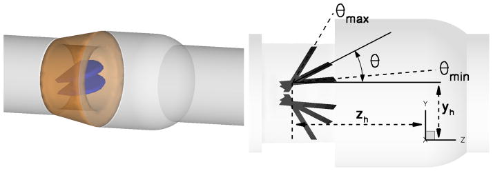
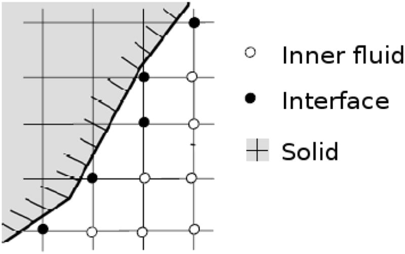
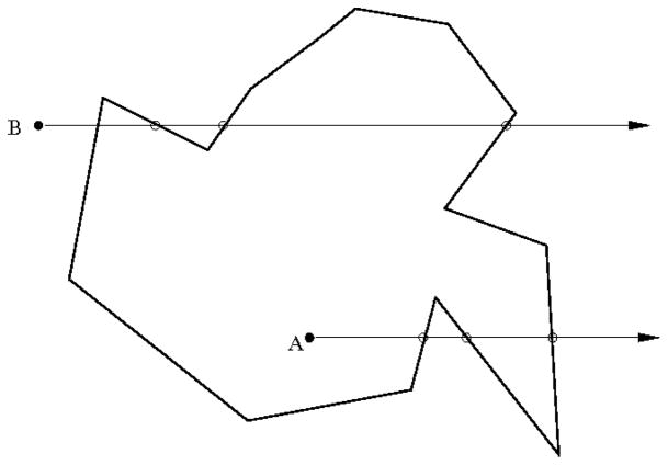
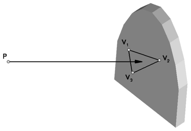
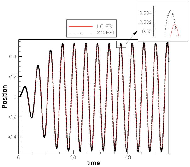
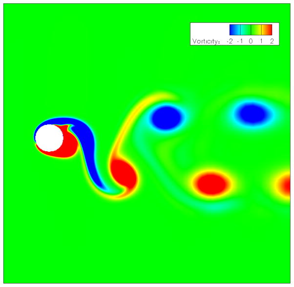
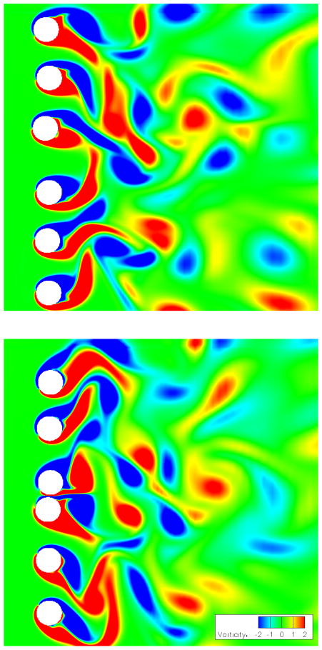
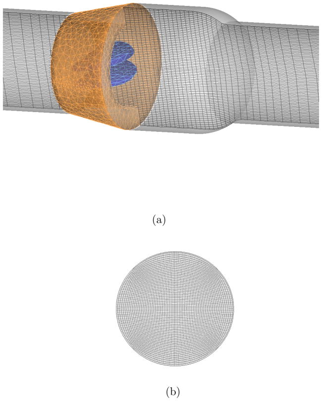
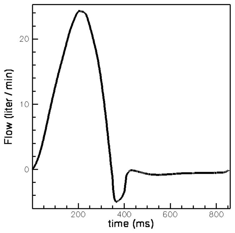
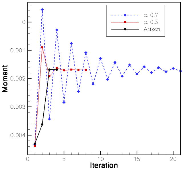
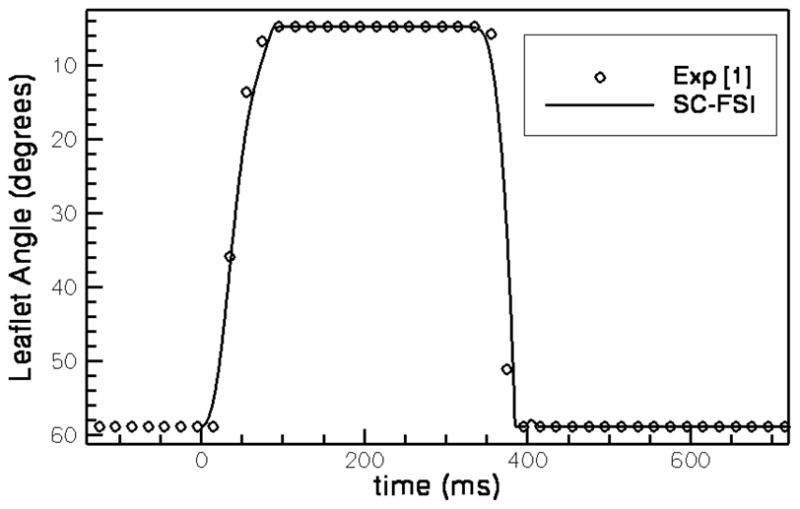
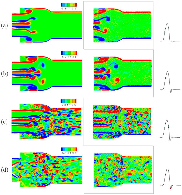
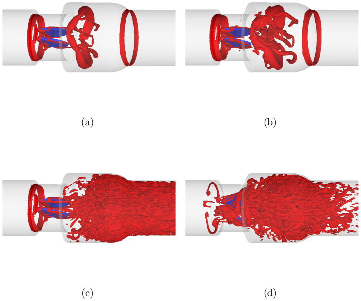
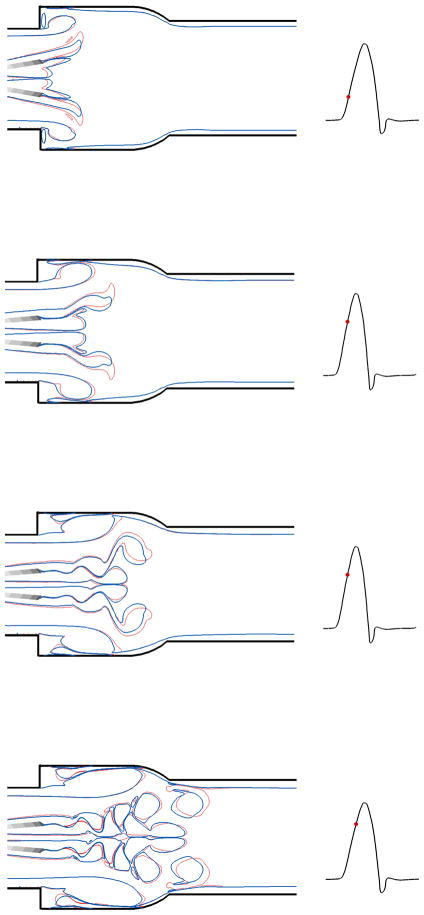
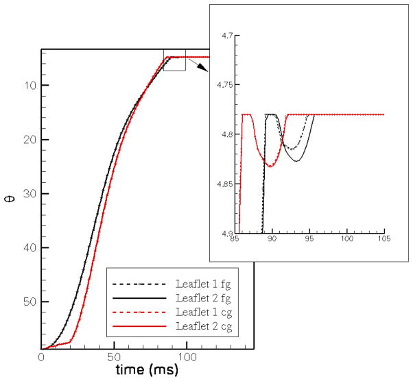
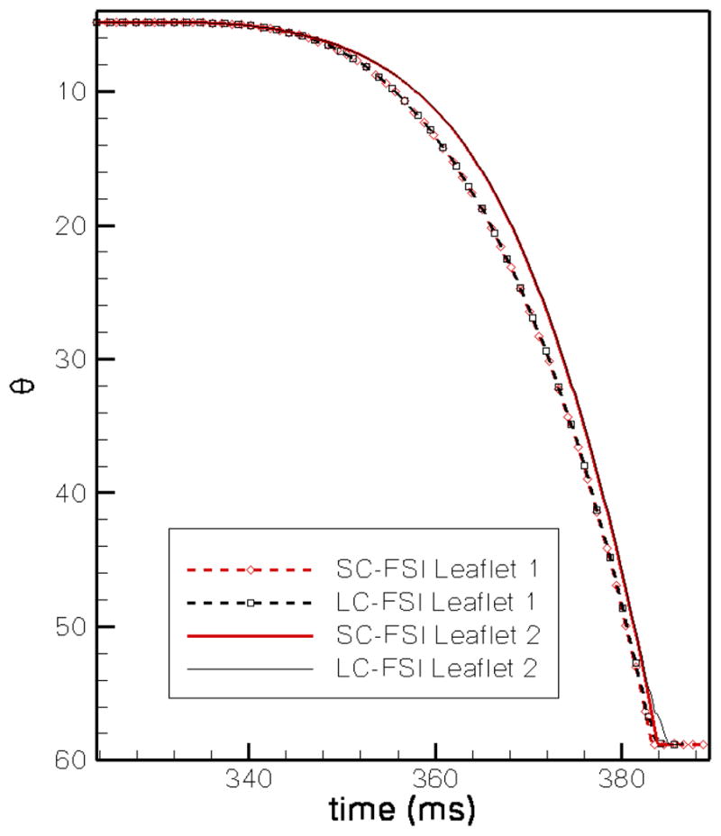
The sharp-interface CURVIB approach of Ge and Sotiropoulos [L. Ge, F. Sotiropoulos, A Numerical Method for Solving the 3D Unsteady Incompressible Navier-Stokes Equations in Curvilinear Domains with Complex Immersed Boundaries, Journal of Computational Physics 225 (2007) 1782-1809] is extended to simulate fluid structure interaction (FSI) problems involving complex 3D rigid bodies undergoing large structural displacements. The FSI solver adopts the partitioned FSI solution approach and both loose and strong coupling strategies are implemented. The interfaces between immersed bodies and the fluid are discretized with a Lagrangian grid and tracked with an explicit front-tracking approach. An efficient ray-tracing algorithm is developed to quickly identify the relationship between the background grid and the moving bodies. Numerical experiments are carried out for two FSI problems: vortex induced vibration of elastically mounted cylinders and flow through a bileaflet mechanical heart valve at physiologic conditions. For both cases the computed results are in excellent agreement with benchmark simulations and experimental measurements. The numerical experiments suggest that both the properties of the structure (mass, geometry) and the local flow conditions can play an important role in determining the stability of the FSI algorithm. Under certain conditions unconditionally unstable iteration schemes result even when strong coupling FSI is employed. For such cases, however, combining the strong-coupling iteration with under-relaxation in conjunction with the Aitken's acceleration technique is shown to effectively resolve the stability problems. A theoretical analysis is presented to explain the findings of the numerical experiments. It is shown that the ratio of the added mass to the mass of the structure as well as the sign of the local time rate of change of the force or moment imparted on the structure by the fluid determine the stability and convergence of the FSI algorithm. The stabilizing role of under-relaxation is also clarified and an upper bound of the required for stability under-relaxation coefficient is derived.
Figures
Similar articles
-
A Numerical Method for Solving the 3D Unsteady Incompressible Navier-Stokes Equations in Curvilinear Domains with Complex Immersed Boundaries.J Comput Phys. 2007 Aug;225(2):1782-1809. doi: 10.1016/j.jcp.2007.02.017. J Comput Phys. 2007. PMID: 19194533 Free PMC article.
-
A sharp interface Lagrangian-Eulerian method for flexible-body fluid-structure interaction.J Comput Phys. 2023 Sep 1;488:112174. doi: 10.1016/j.jcp.2023.112174. Epub 2023 Apr 24. J Comput Phys. 2023. PMID: 37214277 Free PMC article.
-
A parallel overset-curvilinear-immersed boundary framework for simulating complex 3D incompressible flows.Comput Fluids. 2013 Apr 1;77:76-96. doi: 10.1016/j.compfluid.2013.02.017. Comput Fluids. 2013. PMID: 23833331 Free PMC article.
-
A sharp interface Lagrangian-Eulerian method for rigid-body fluid-structure interaction.J Comput Phys. 2021 Oct 15;443:110442. doi: 10.1016/j.jcp.2021.110442. Epub 2021 May 18. J Comput Phys. 2021. PMID: 34149063 Free PMC article.
-
Fluid-structure interaction modeling in cardiovascular medicine - A systematic review 2017-2019.Med Eng Phys. 2020 Apr;78:1-13. doi: 10.1016/j.medengphy.2020.01.008. Epub 2020 Feb 17. Med Eng Phys. 2020. PMID: 32081559
Cited by
-
An immersogeometric variational framework for fluid-structure interaction: application to bioprosthetic heart valves.Comput Methods Appl Mech Eng. 2015 Feb 1;284:1005-1053. doi: 10.1016/j.cma.2014.10.040. Comput Methods Appl Mech Eng. 2015. PMID: 25541566 Free PMC article.
-
Toward patient-specific simulations of cardiac valves: state-of-the-art and future directions.J Biomech. 2013 Jan 18;46(2):217-28. doi: 10.1016/j.jbiomech.2012.10.026. Epub 2012 Nov 20. J Biomech. 2013. PMID: 23174421 Free PMC article. Review.
-
A Newton-Krylov method with an approximate analytical Jacobian for implicit solution of Navier-Stokes equations on staggered overset-curvilinear grids with immersed boundaries.J Comput Phys. 2017 Feb 15;331:227-256. doi: 10.1016/j.jcp.2016.11.033. Epub 2016 Nov 25. J Comput Phys. 2017. PMID: 28042172 Free PMC article.
-
Review of numerical methods for simulation of mechanical heart valves and the potential for blood clotting.Med Biol Eng Comput. 2017 Sep;55(9):1519-1548. doi: 10.1007/s11517-017-1688-9. Epub 2017 Jul 26. Med Biol Eng Comput. 2017. PMID: 28744828 Review.
-
A numerical study of fish adaption behaviors in complex environments with a deep reinforcement learning and immersed boundary-lattice Boltzmann method.Sci Rep. 2021 Jan 18;11(1):1691. doi: 10.1038/s41598-021-81124-8. Sci Rep. 2021. PMID: 33462281 Free PMC article.
References
-
- Dasi LP, Ge L, Simon HA, Sotiropoulos F, Yoganathan AP. Vorticity dynamics of a bileaflet mechanical valve in an axisymmetric aorta. Physics of Fluids. 2007;19:067105.
-
- Donea J, Giuliani S, Halleux J. An arbitrary Lagrangian-Eulerian finite element method for transient dynamic fluid-structure interactions. Computer Methods in Applied Mechanics and Engineering. 1982;33(1–3):689–723.
-
- Peskin CS. Flow patterns around heart valves: A numerical method. Journal of Computational Physics. 1972;10:252–271.
-
- Farhat C, Lesoinne M, LeTallec P. Load and motion transfer algorithms for fluid/structure interaction problems with non-matching discrete interfaces: Momentum and energy conservation, optimal discretization and application to aeroelasticity. Computer methods in applied mechanics and engineering. 1998;157(1):95–114.
Grants and funding
LinkOut - more resources
Full Text Sources