

Review
doi: 10.3174/ajnr.A2211.
Epub 2010 Oct 28.
Imaging evaluation of intrathecal baclofen pump-catheter systems
Affiliations
- PMID: 21030478
- PMCID: PMC7966068
- DOI: 10.3174/ajnr.A2211
Item in Clipboard
Review
Imaging evaluation of intrathecal baclofen pump-catheter systems
AJNR Am J Neuroradiol.
2011 Aug.
Abstract
ITB pumps are widely used in the treatment of intractable spasticity for many clinical indications, including cerebral palsy and spinal cord injury. High-dose intrathecal administration places the patient at significant risk for withdrawal in the event of device malfunction, necessitating rapid and complete evaluation of the pump-catheter system. This article reviews the approach to imaging evaluation of ITB pump-catheter systems, with specific emphasis on radiography, fluoroscopy, CT, and nuclear scintigraphy.
Figures

Illustration depicting an intrathecal baclofen pump implanted in the anterolateral abdominal wall with a catheter coursing subcutaneously around the patient to enter the spinal canal.

Photographic (A) and radiographic (B) representations of the SynchroMed model EL intrathecal baclofen pump depicting the pump rotor (red ring), reservoir port (yellow arrow), catheter-access port (blue arrow), and the pump connector (magenta arrow). (Copyrighted images reprinted with permission of Medtronic, Inc.)

Photographic (A) and radiographic (B) representations of the SynchroMed model II intrathecal baclofen pump depicting the pump roller (red ring), reservoir port (yellow arrow), catheter-access port (blue arrow), and pump connector (magenta arrow).

An AP radiograph demonstrates a kinked/folded catheter (yellow arrow) within the subcutaneous tissue.

AP (A) and lateral (B) radiographs demonstrating a discontinuous segment of the catheter, with broken catheter ends in the subcutaneous tissue of the lower back (white arrow) and the spinal canal (yellow arrow).

A, Initial fluoroscopic spot image (A) demonstrating disconnection at the pump connector (arrow). B, A small amount of contrast extravasation (yellow arrow) is seen after injection of contrast via the catheter-access port (fluoroscopic spot image). C, A lateral fluoroscopic spot image better demonstrates contrast extravasation at the connector (yellow arrow) and reveals a collection of pooled contrast (yellow outline) posterior to the pump. D and E, Photographs demonstrate the disconnection at the connector after surgical explantation.

Lateral fluoroscopic spot image (A) reveals extravasating contrast (yellow arrows) from an apparently intact catheter. Further extravasation (arrows) is demonstrated during continued injection (B), consistent with catheter perforation.
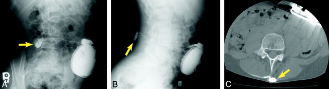
AP (A) and lateral (B) radiographs as well as an axial CT (C) image show extravasated contrast material (yellow arrows) surrounding the catheter connector in the subcutaneous tissues of the mid-lower back, where it turns anteriorly toward the spinal canal.

Axial CT image demonstrates an extraluminal contrast collection (yellow arrows) adjacent to an apparently intact catheter. This contrast extravasation was not identified at fluoroscopic evaluation performed during contrast injection.

A, An axial CT image reveals a pocket of extravasated contrast (blue outline) both anterior and posterior to the pump (red outline) in the anterior abdominal wall. B and C, Photographs taken after surgical explantation demonstrate breakage at the connector (black arrows).
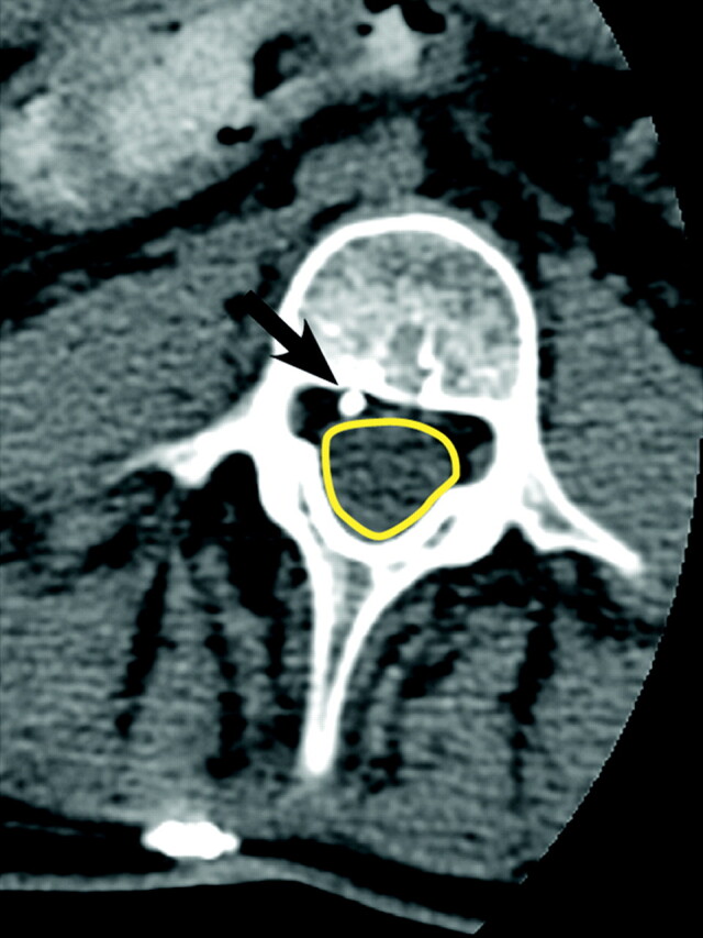
An axial noncontrast CT image clearly shows the catheter (black arrow) outside the thecal sac (yellow outline) in the epidural space.

Scintigraphic image obtained 48 hours after injection of 1-mCi 111In DTPA into the medication reservoir reveals nonpatency of the catheter system with no intrathecal contrast visualized. The area of photopenia represents the position of the pump (yellow outline). Radioactivity within the pump represents the medication reservoir (blue outline). Radiopharmaceutical is observed within the proximal catheter (red dotted line) and ends abruptly (red arrow). Note that the etiology of the nonpatency of the catheter cannot be determined from this study.
References
-
- Penn RD, Kroin JS. Intrathecal baclofen alleviates spinal cord spasticity. Lancet 1984;1:1078. - PubMed
-
- Dralle D, Muller H, Zierski J, et al. . Intrathecal baclofen for spasticity. Lancet 1985;2:1003 - PubMed
-
- Gilmartin R, Bruce D, Storrs BB, et al. . Intrathecal baclofen for management of spastic cerebral palsy: multicenter trial. J Child Neurol 2000;15:71–77 - PubMed
-
- Van Schaeybroeck P, Nuttin B, Lagae L, et al. . Intrathecal baclofen for intractable cerebral spasticity: a prospective placebo-controlled, double-blind study. Neurosurgery 2000;46:603–09, discussion 609–12 - PubMed
-
- Becker R, Alberti O, Bauer BL. Continuous intrathecal baclofen infusion in severe spasticity after traumatic or hypoxic brain injury. J Neurol 1997;244:160–66 - PubMed
Publication types
MeSH terms
Substances
LinkOut - more resources
Full Text Sources
Medical