Editorial
. 2010 Dec;121(12):1976-8.
doi: 10.1016/j.clinph.2010.05.020. Epub 2010 Jun 17.

Electrode montages for tDCS and weak transcranial electrical stimulation: role of "return" electrode's position and size

Editorial

Electrode montages for tDCS and weak transcranial electrical stimulation: role of "return" electrode's position and size

M Bikson et al. Clin Neurophysiol. 2010 Dec.
No abstract available


Figures

Figure 1
Figure 1
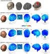
Effect of “return” electrode’s position and size on cortical electric fields induced by a 4 cm × 4 cm “active” electrode over the left primary motor cortex. An individualized FEM head model was created from MRI scans of an adult male at 1 mm × 1mm × 1 mm resolution (Soterix LLC, NY, USA). The head was segmented into compartments representing the brain, CSF, skull, scalp, muscle, eyes, and air. The laplace equation was solved and current densities corresponding to 1 mA total current was applied. Induced cortical electric field (EF) magnitude maps for the different electrode montages were determined. All false color maps were generated between 0 and 0.44 V/m; the peak cortical EF magnitude induced in Montage A. Top row: Sample segmentation masks. A: Stimulation with a 4 cm × 4 cm return electrode over the contralateral forehead (Montage A) results in significant cortical activation in the right frontal lobe, as well as diffuse and clustered activation between the electrodes. B: Stimulation a 4 cm × 4 cm return electrode on the contralateral mastoid (approximating an extra-cephalic electrode; Montage B) results in cortical electric field on the left hemisphere as current preferentially flows down the posterior regions of the brain and through the brain stem. C: Stimulation with a 16 cm × 4 cm electrode wrapped around the contralateral forehead (Montage C) results in diffuse and clustered cortical electric fields. The insets (A.3, B.3, C.3) highlight gyri/sulci modulation directly under the pad (with the “lighting on” feature). For montages with different placements of return electrode (Montage A and B), the pattern of cortical electric fields directly under the “active’ electrode (inset) was distinct.

Comment on

References

    1. Accornero N, Li Voti P, La Riccia M, Gregori B. Visual evoked potentials modulation during direct current cortical polarization. Exp Brain Res. 2007;178(2):261–266. - PubMed
    1. Baker JM, Rorden C, Fridriksson J. Using Transcranial Direct-Current Stimulation to treat stroke patients with aphasia. Stroke. 2010 [Epub] - PMC - PubMed
    1. Bikson M, Bulow P, Stiller JW, Datta A, Battaglia F, Karnup SV, et al. Transcranial direct current stimulation for major depression: a general system for quantifying transcranial electrotherapy dosage. Curr Treat Options Neurol. 2008;10:377–385. - PubMed
    1. Butson CR, Cooper SE, Henderson JM, McIntyre CC. Patient specific analysis of the volume of tissue activated during deep brain stimulation. Neuroimage. 2007;34:661–670. - PMC - PubMed
    1. Datta A, Elwassif M, Battaglia F, Bikson M. Transcranial current stimulation focality using disc and ring electrode configurations:FEM analysis. J Neural Eng. 2008;5:163–174. - PubMed