Development of a mandibular motion simulator for total joint replacement
- PMID: 21050636
- PMCID: PMC4638329
- DOI: 10.1016/j.joms.2010.05.085
Development of a mandibular motion simulator for total joint replacement
Abstract
Purpose: The purpose of this study was to develop a motion simulator capable of recreating and recording the full range of mandibular motions in a cadaveric preparation for an intact temporomandibular joint (TMJ) and after total joint replacement.
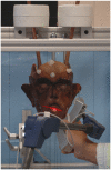
Material and methods: A human cadaver head was used. Two sets of tracking balls were attached to the forehead and mandible, respectively. Computed tomographic (CT) scan was performed and 3-dimensional CT models of the skull were generated. The cadaver head was then dissected to attach the muscle activation cables and mounted onto the TMJ simulator. Realistic jaw motions were generated through the application of the following muscle forces: lateral pterygoid muscle, suprahyoid depressors (geniohyoid, mylohyoid, and digastric muscles), and elevator muscles. To simulate muscle contraction, cables were inserted into the mandible at the center area of each muscle's attachment. To provide a minimum mouth closing force at the initial position, the elevator muscles were combined at the anterior mandible. During mandibular movement, each motion was recorded using a high-resolution laser scanner. The right TMJ of the same head was reconstructed with a total TMJ prosthesis. The same forces were applied and the jaw motions were recorded again. CT scan was performed and 3-dimensional CT models of the skull with TMJ prosthesis were generated.
Results: Mandibular motions, before and after TMJ replacement, with and without lateral pterygoid muscle reattachment, were re-created in a cadaveric preparation. The laser-scanned data during the mandibular motion were used to drive 3-dimensional CT models. A movie for each mandibular motion was subsequently created for motion path analysis. Compared with mandibular motion before TMJ replacement, mandibular lateral and protrusive motions after TMJ replacement, with and without lateral pterygoid muscle reattachment, were greatly limited. The jaw motion recorded before total joint replacement was applied to the mandibular and prostheses models after total TMJ replacement. The condylar component was observed sinking into the fossa during jaw motion.
Conclusion: A motion simulator capable of re-creating and recording full range of mandibular motions in a cadaveric preparation has been developed. It can be used to simulate mandibular motions for the intact TMJ and total joint prosthesis, and to re-create and record their full range of mandibular motions. In addition, the full range of the recorded motion can be re-created as motion images in a computer. These images can be used for motion path analysis and to study the causation of limited range of motion after total joint replacement and strategies for improvement.
Copyright © 2011 American Association of Oral and Maxillofacial Surgeons. Published by Elsevier Inc. All rights reserved.
Figures


Similar articles
-
Load transfer in Christensen(®) TMJ in alloplastic total joint replacement for two different mouth apertures.J Craniomaxillofac Surg. 2014 Oct;42(7):1442-9. doi: 10.1016/j.jcms.2014.04.008. Epub 2014 May 2. J Craniomaxillofac Surg. 2014. PMID: 24954763
-
Electromyographic activity of the human lateral pterygoid muscle during contralateral and protrusive jaw movements.Arch Oral Biol. 1999 Mar;44(3):269-85. doi: 10.1016/s0003-9969(98)00117-4. Arch Oral Biol. 1999. PMID: 10217518
-
Finite element analysis of stresses in the maxillary and mandibular dental arches and TMJ articular discs during clenching into maximum intercuspation, anterior and unilateral posterior occlusion.Stomatologija. 2007;9(4):121-8. Stomatologija. 2007. PMID: 18303277
-
Functional states of mandibular movements and synovial pumps of the temporomandibular joint. Is it possible to provide a biomechanically correct replacement for the TMJ?Ann Anat. 2012 Mar 20;194(2):200-7. doi: 10.1016/j.aanat.2011.10.004. Epub 2011 Oct 14. Ann Anat. 2012. PMID: 22079779 Review.
-
Measurement of normal and pathological mandibular and temporomandibular joint kinematics: A systematic review.J Biomech. 2020 Oct 9;111:109994. doi: 10.1016/j.jbiomech.2020.109994. Epub 2020 Sep 3. J Biomech. 2020. PMID: 32971491
Cited by
-
Biomechanical evaluation of the human mandible after temporomandibular joint replacement under different biting conditions.Sci Rep. 2021 Jul 7;11(1):14034. doi: 10.1038/s41598-021-93564-3. Sci Rep. 2021. PMID: 34234245 Free PMC article.
-
Prediction of condylar movement envelope surface based on facial morphology.Heliyon. 2023 Jul 7;9(7):e17769. doi: 10.1016/j.heliyon.2023.e17769. eCollection 2023 Jul. Heliyon. 2023. PMID: 37483714 Free PMC article.
-
Mandibular kinematics and maximum voluntary bite force following segmental resection of the mandible without or with reconstruction.Clin Oral Investig. 2018 May;22(4):1707-1716. doi: 10.1007/s00784-017-2263-3. Epub 2017 Nov 7. Clin Oral Investig. 2018. PMID: 29116495
-
Understanding Occlusion and Temporomandibular Joint Function Using Deep Learning and Predictive Modeling.Clin Exp Dent Res. 2024 Dec;10(6):e70028. doi: 10.1002/cre2.70028. Clin Exp Dent Res. 2024. PMID: 39563180 Free PMC article. Review.
-
Designing customized temporomandibular fossa prosthesis based on envelope surface of condyle movement: validation via in silico musculoskeletal simulation.Front Bioeng Biotechnol. 2023 Oct 31;11:1273263. doi: 10.3389/fbioe.2023.1273263. eCollection 2023. Front Bioeng Biotechnol. 2023. PMID: 38026896 Free PMC article.
References
-
- Spagnoli DB, Koslin MG. Temporomandibular joint. In: Piecuch JF, editor. OMS Knowledge Update. ed 1 Vol 3. American Association of Oral and Maxillofacial Surgeons; Chicago, IL: 2001. p. 53.
-
- Mercuri LG. The use of alloplastic prostheses for temporomandibular joint reconstruction. J Oral Maxillofac Surg. 2000;58:70. - PubMed
-
- Wolford LM, Pitta MC, Reiche-Fischel O, et al. TMJ concepts/Techmedica custom-made TMJ total joint prosthesis: 5-year follow-up study. Int J Oral Maxillofac Surg. 2003;32:268. - PubMed
-
- Wolford LM, Dingwerth DJ, Talwar RM, et al. Comparison of 2 temporomandibular joint total joint prosthesis systems. J Oral Maxillofac Surg. 2003;61:685. - PubMed
-
- Mercuri LG, Wolford LM, Sanders B, et al. Long-term follow-up of the CAD/CAM patient fitted total temporomandibular joint reconstruction system. J Oral Maxillofac Surg. 2002;60:1440. - PubMed
Publication types
MeSH terms
Grants and funding
LinkOut - more resources
Full Text Sources
Miscellaneous

