

Temporomandibular joint and 3.0 T pseudodynamic magnetic resonance imaging. Part 1: evaluation of condylar and disc dysfunction
- PMID: 21062941
- PMCID: PMC3520213
- DOI: 10.1259/dmfr/29741224
Temporomandibular joint and 3.0 T pseudodynamic magnetic resonance imaging. Part 1: evaluation of condylar and disc dysfunction
Abstract
Objectives: This study describes an improved method for examining and diagnosing temporomandibular joint (TMJ) dynamics by 3.0 T pseudodynamic MRI.
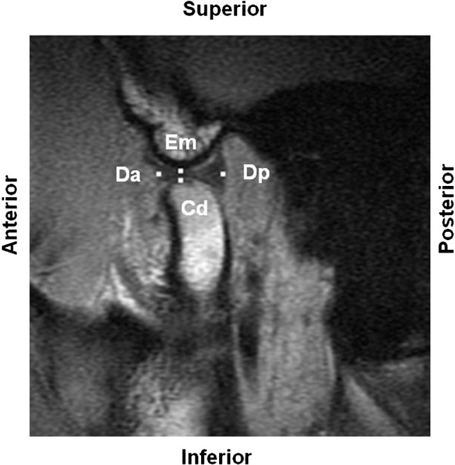
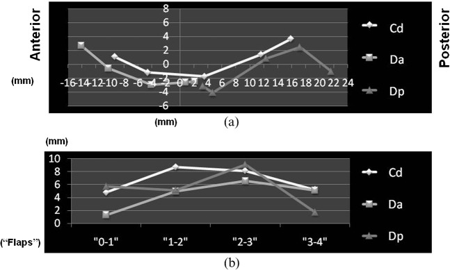
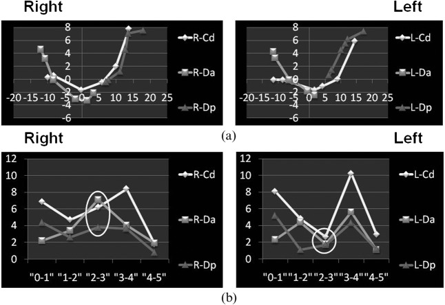
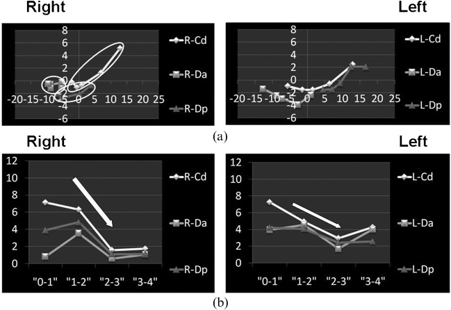
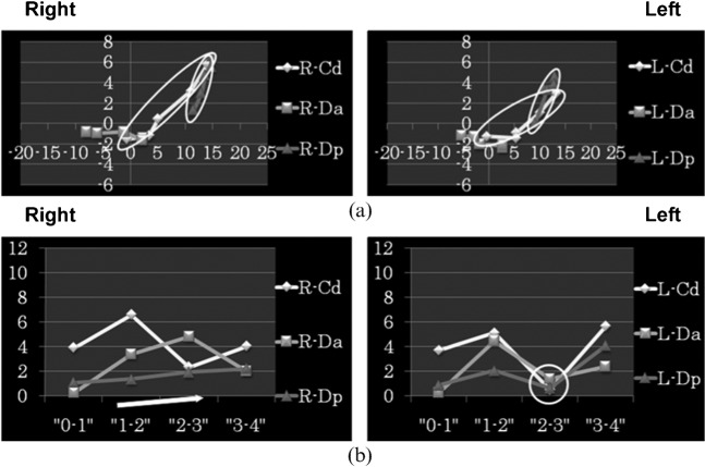
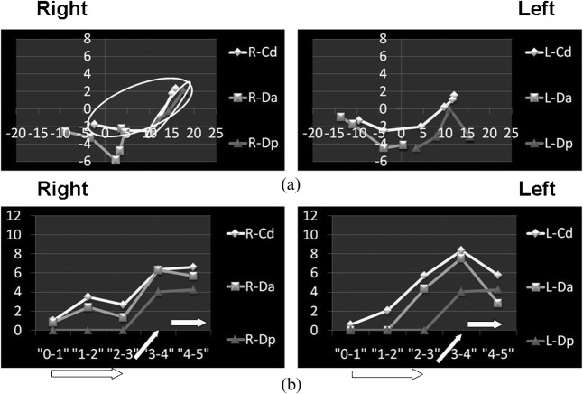
Methods: Clinical observation and conventional static MRI of volunteers (one without and eight with TMJ arthrosis) were followed by 3.0 T pseudodynamic MRI in positions ranging from the mouth closed to mouth fully opened. Condylar head (Cd), articular disc anterior border (Da) and articular disc posterior border (Dp) were digitized on sagittal images to determine trajectory and velocity patterns.
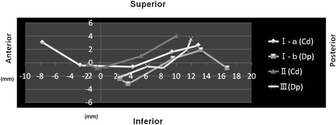
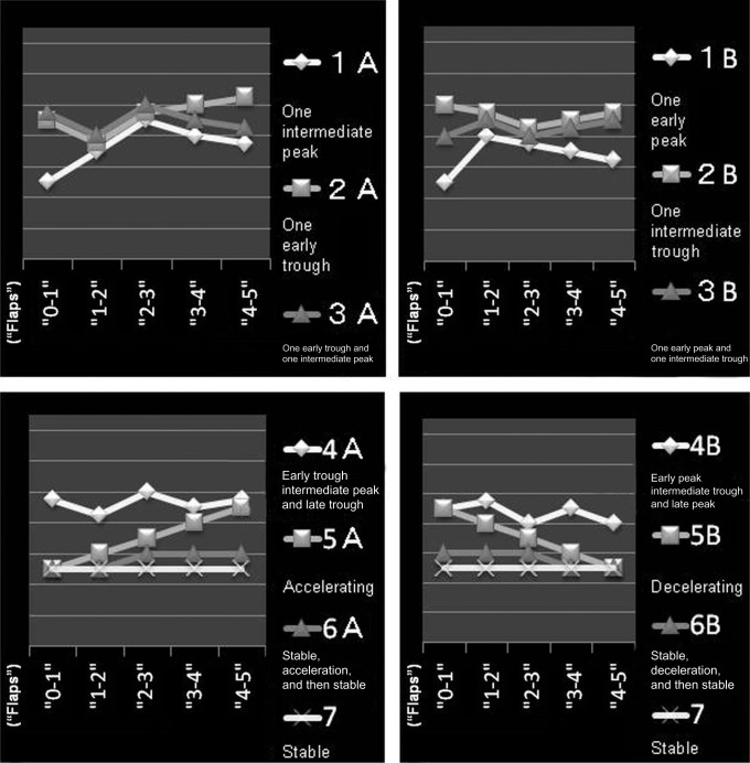
Results: Patients were divided into three groups based on the presence or absence of dysfunction: Group 1, no dysfunction on the right or left side of the TMJ; Group 2, dysfunction on the right or left side of the TMJ; and Group 3, dysfunction on both the right and left sides of the TMJs. In 75% of patients (12 of 16 joints), pseudodynamic TMJ analysis was useful for determining a functional abnormality. Using a points system based on three trajectory and seven velocity patterns, discs with adhesion and perforation had significantly fewer points than discs with anterior displacement (with and without reduction) and discs with no abnormality (P = 0.019 < 0.05).
Conclusions: Trajectory and velocity patterns based on 3.0 T pseudodynamic MRI identified the affected side and determined the extent of morbidity in the Cd as well as the Da and Dp. The typical abnormal movement pattern of discs with anterior displacement (with and without reduction) and pathological structural changes of the articular disc (such as adhesion and perforation) could be identified.
Figures
References
-
- Chen J, Buckwalter K. Displacement analysis of the temporomandibular condyle from magnetic resonance images. J Biomech 1993;26:1455–1462 - PubMed
-
- Eberhard D, Bantleon HP, Steger W. Functional magnetic resonance imaging of temporomandibular joint disorders. Eur J Orthod 2000;22:489–497 - PubMed
-
- Liu ZJ, Yamagata K, Kuroe K, Suenaga S, Noikura T, Ito G. Morphological and positional assessments of TMJ components and lateral pterygoid muscle in relation to symptoms and occlusion of patients with temporomandibular disorders. J Oral Rehabil 2000;27:860–874 - PubMed
-
- Dorsay TA, Youngberg RA, Orr FE. Cine MRI diagnosis and posttherapeutic evaluation of an adherent TMJ disc: a case report. J Oral Maxillofac Surg 1994;52:1220–1222 - PubMed
-
- Katzberg RW, Tallents RH. Normal and abnormal temporomandibular joint disc and posterior attachment as depicted by magnetic resonance imaging in symptomatic and asymptomatic subjects. J Oral Maxillofac Surg 2005;63:1155–1161 - PubMed
Publication types
MeSH terms
LinkOut - more resources
Full Text Sources
Medical
