. 2011 Jan 21;11(2):315-22.
doi: 10.1039/c0lc00358a. Epub 2010 Nov 9.

Cost-effective and compact wide-field fluorescent imaging on a cell-phone

Affiliations

Cost-effective and compact wide-field fluorescent imaging on a cell-phone

Hongying Zhu et al. Lab Chip. .

Erratum in

  • Lab Chip. 2011 Dec 21;11(24):4279

Abstract

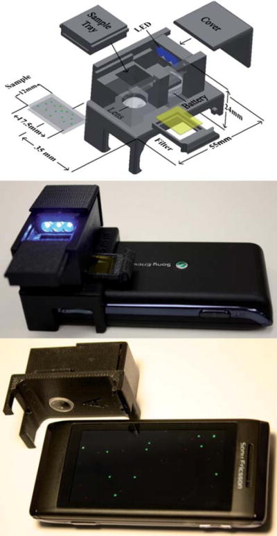
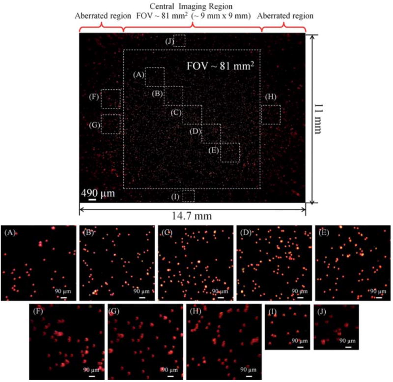
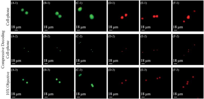
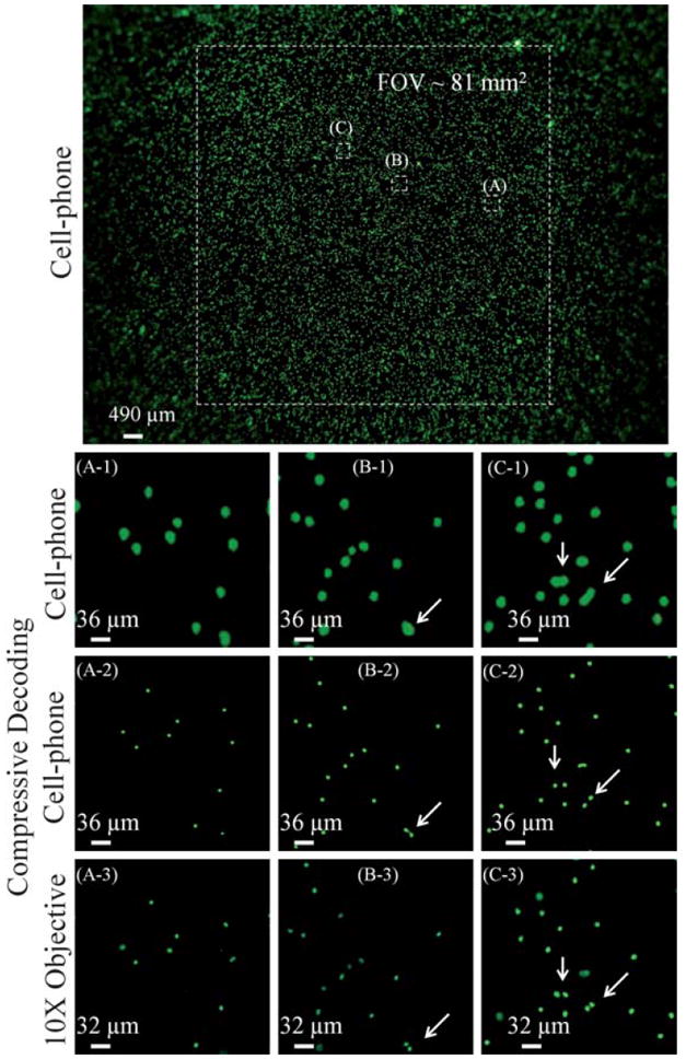
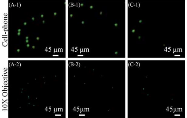
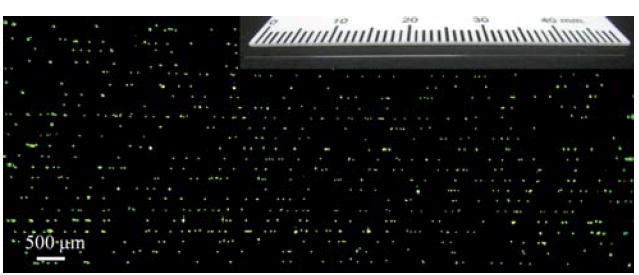
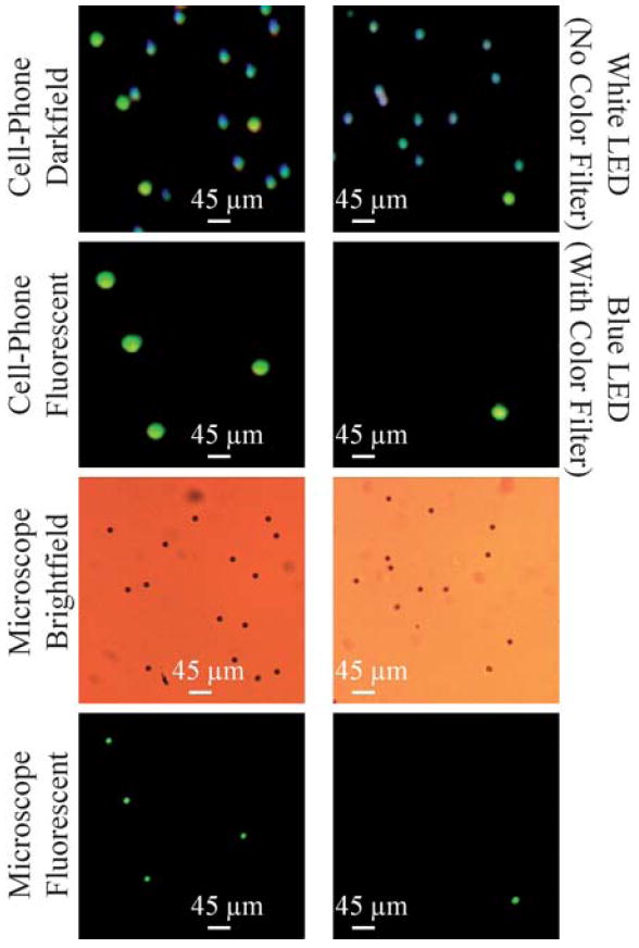
We demonstrate wide-field fluorescent and darkfield imaging on a cell-phone with compact, light-weight and cost-effective optical components that are mechanically attached to the existing camera unit of the cell-phone. For this purpose, we used battery powered light-emitting diodes (LEDs) to pump the sample of interest from the side using butt-coupling, where the pump light was guided within the sample cuvette to uniformly excite the specimen. The fluorescent emission from the sample was then imaged using an additional lens that was positioned right in front of the existing lens of the cell-phone camera. Because the excitation occurs through guided waves that propagate perpendicular to our detection path, an inexpensive plastic colour filter was sufficient to create the dark-field background required for fluorescent imaging, without the need for a thin-film interference filter. We validate the performance of this platform by imaging various fluorescent micro-objects in 2 colours (i.e., red and green) over a large field-of-view (FOV) of ∼81 mm(2) with a raw spatial resolution of ∼20 μm. With additional digital processing of the captured cell-phone images, through the use of compressive sampling theory, we demonstrate ∼2 fold improvement in our resolving power, achieving ∼10 μm resolution without a trade-off in our FOV. Further, we also demonstrate darkfield imaging of non-fluorescent specimen using the same interface, where this time the scattered light from the objects is detected without the use of any filters. The capability of imaging a wide FOV would be exceedingly important to probe large sample volumes (e.g., >0.1 mL) of e.g., blood, urine, sputum or water, and for this end we also demonstrate fluorescent imaging of labeled white-blood cells from whole blood samples, as well as water-borne pathogenic protozoan parasites such as Giardia Lamblia cysts. Weighing only ∼28 g (∼1 ounce), this compact and cost-effective fluorescent imaging platform attached to a cell-phone could be quite useful especially for resource-limited settings, and might provide an important tool for wide-field imaging and quantification of various lab-on-a-chip assays developed for global health applications, such as monitoring of HIV+ patients for CD4 counts or viral load measurements.


Figures

Fig. 1
Fig. 1
(Top) Schematic diagram of the designed optical attachment for wide-field fluorescent imaging on a cell-phone. (Middle and Bottom) Different views of the fluorescent imager prototype. This entire attachment to the cell-phone weighs ~28 g (~1 ounce) and has dimensions of ~3.5 × 5.5 × 2.4 cm. This compact and light-weight unit can be repeatedly attached and detached to the cell-phone body without the need for any fine alignment, making its interface fairy easy to use.
Fig. 2
Fig. 2
Imaging performance of the cell-phone fluorescent microscope shown in Fig. 1 is demonstrated using fluorescent beads (10 μm diameter; excitation/emission: 580 nm/605 nm). The central field-of-view of each cell-phone image is ~8l mm2, which exhibits a decent imaging performance. The edges of the image, which lie outside of this central region exhibit aberrations, and therefore are not included in the reported field-of-view. For counting purposes, however, those aberrated regions could still be useful despite their poorer image quality. Note that all the scale bars in zoomed frames (A–J) have the same length.
Fig. 3
Fig. 3
Spatial resolution of the cell-phone fluorescent microscope shown in Fig. 1 is illustrated using green and red fluorescent beads. The top row shows raw cell-phone images of the particles which demonstrate ~20 μm resolution in both of the fluorescent colors, e. g., the particles in B-1 and E-1 can be resolved from each other by our cell-phone microscope. The middle row illustrates the compressive decoding results of the top row cell-phone images which can now resolve ~10 μm spaced fluorescent particles in both green and red colors, as shown in C-2 and F-2, respectively. The bottom row illustrates, for comparison purposes, 10× microscope-objective (NA = 0.25) images of the same samples acquired with a conventional fluorescent microscope. Note that because the samples were suspended in a solution, their relative orientations might be slightly shifted in microscope comparison images. Markers were used on the sample slides to be able to conveniently match the microscope images to their corresponding cell-phone images.
Fig. 4
Fig. 4
Imaging performance of our cell-phone fluorescent microscope is demonstrated using labeled white blood cells. Microscope objective (10×, NA = 0.25) images of the same samples, acquired with a conventional fluorescent microscope, are also provided for comparison purposes. White arrows point to cells that can be resolved using compressive decoding, which further demonstrate our improved resolving power similar to Fig. 3. Note that because the samples were suspended in a solution, their relative orientations might be slightly shifted in microscope comparison images, as a result of which the FOV and the scale-bars of the microscope images are slightly different when compared to the cell-phone images.
Fig. 5
Fig. 5
(Top) Giardia Lamblia cysts that are imaged using the fluorescent cell-phone microscope of Fig. 1. (Bottom) Microscope objective (10×, NA = 0.25) images of the same samples are also provided for comparison purposes. Note that because the samples were suspended in a solution, their relative orientations might be slightly shifted in the microscope comparison images. In (B-2) and (C-2) there are 2 dead-pixels at the microscope images which do not show up in our cell-phone images.
Fig. 6
Fig. 6
Fluorescent samples can also be imaged within micro-capillaries using our cell-phone based fluorescent microscope. In this case, simple capillary action is sufficient to load the specimen into a capillary tube. Each capillary, when loaded with the sample solution, acts as a wave-guide for pump photons, such that efficient excitation of the samples could be achieved as illustrated in this figure for 10 μm fluorescent beads that were loaded into several capillary tubes in parallel. The inset figure at the top corner illustrates one of the capillaries used in this work (100 μm inner diameter; 170 μm outer diameter). For further information please refer to Supplementary Fig. 1.
Fig. 7
Fig. 7
Darkfield imaging capability of our cell-phone microscope (Fig. 1) is demonstrated using a mixture of fluorescent and non-fluorescent 10 μm beads. (Top row) Darkfield images of two different zoomed regions of the sample are illustrated. Because the illumination was achieved using a white LED (without any color filter in front of the sensor), the scattered light from non-fluorescent beads creates their darkfield images. The fluorescent beads can still be excited using this white LED and therefore their green fluorescent emission is also visible in this darkfield image. (Second row) Fluorescent images of the same FOV are illustrated using the cell-phone microscope. The illumination was achieved using a blue LED which efficiently pumped the green fluorescent beads as evident in their images. The non-fluorescent beads do not show up in this image since a color filter in front of the cell-phone sensor rejected the pump wavelength. (Third row) Conventional bright-field microscope images of the same FOV are illustrated using a 10× objective lens for comparison purposes. (Bottom row) Conventional fluorescent microscope images of the same FOV are illustrated using a 10× objective lens for comparison purposes. Note also that because the samples were suspended in a solution, their relative orientations might be slightly shifted in their microscope comparison images.

Similar articles

Cited by

References

    1. International Telecommunication Union. Market information and statistics. 2010. http://www.itu.int/ITU-D/ict/statistics/index.html.
    1. Woodward B, Istepanian RSH, Richards CI. IEEE Trans Inf Technol Biomed. 2001;5:13–15. - PubMed
    1. Martinez AW, Philips ST, Carrilho E, Thomas SW, III, Sindi Hayat, Whitesides GM. Anal Chem. 2008;80:3699–3707. - PMC - PubMed
    1. Ruano-López JM, Agirregabiria M, Olabarria G, Verdoy D, Bang DD, Bu M, Wolff A, Voigt A, Dziuban JA, Walczak R, Berganzo J. Lab Chip. 2009;9:1495–1499. - PubMed
    1. Granot Y, Ivorra A, Rubinsky B. PLoS One. 2008;3:e2075. - PMC - PubMed

Publication types