

Adjustment of the lateral and longitudinal size of scanned proton beam spots using a pre-absorber to optimize penumbrae and delivery efficiency
- PMID: 21076194
- PMCID: PMC3001334
- DOI: 10.1088/0031-9155/55/23/S10
Adjustment of the lateral and longitudinal size of scanned proton beam spots using a pre-absorber to optimize penumbrae and delivery efficiency
Abstract
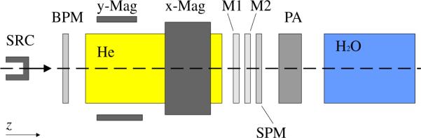
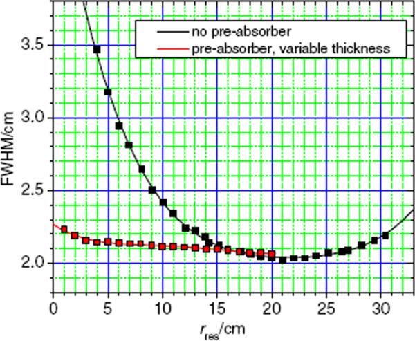
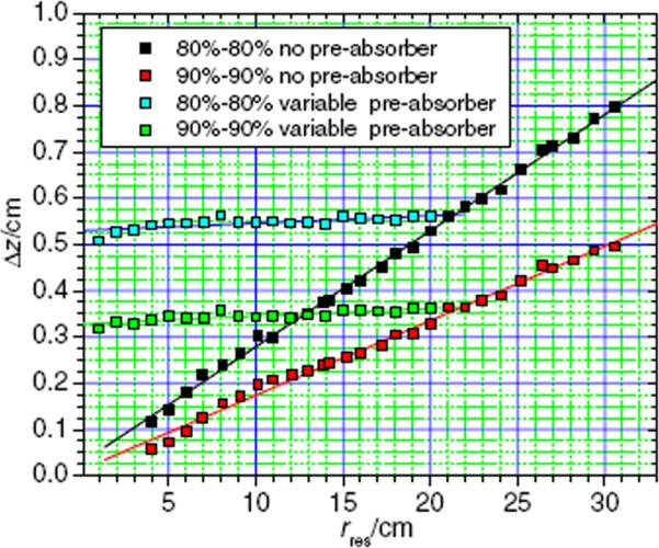
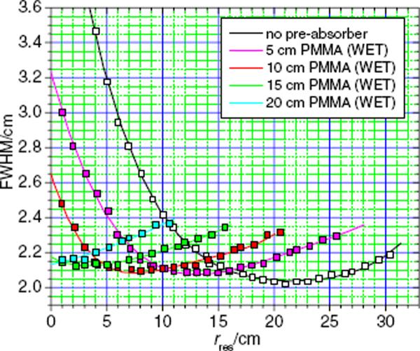
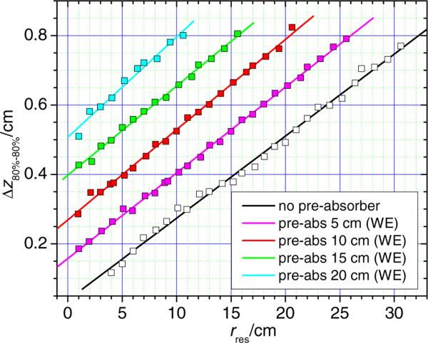
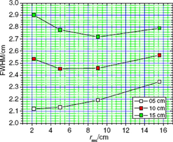
In scanned-beam proton therapy, the beam spot properties, such as the lateral and longitudinal size and the minimum achievable range, are influenced by beam optics, scattering media and drift spaces in the treatment unit. Currently available spot scanning systems offer few options for adjusting these properties. We investigated a method for adjusting the lateral and longitudinal spot size that utilizes downstream plastic pre-absorbers located near a water phantom. The spot size adjustment was characterized using Monte Carlo simulations of a modified commercial scanned-beam treatment head. Our results revealed that the pre-absorbers can be used to reduce the lateral full width at half maximum (FWHM) of dose spots in water by up to 14 mm, and to increase the longitudinal extent from about 1 mm to 5 mm at residual ranges of 4 cm and less. A large factor in manipulating the lateral spot sizes is the drift space between the pre-absorber and the water phantom. Increasing the drift space from 0 cm to 15 cm leads to an increase in the lateral FWHM from 2.15 cm to 2.87 cm, at a water-equivalent depth of 1 cm. These findings suggest that this spot adjustment method may improve the quality of spot-scanned proton treatments.
Figures
References
-
- Akagi T, Higashi A, Tsugami H, Sakamoto H, Masuda Y, Hishikawa Y. Ridge filter design for proton therapy at Hyogo Ion Beam Medical Center. Phys. Med. Biol. 2003;48:N301–12. - PubMed
-
- Bues M, Newhauser WD, Titt U, Smith AR. Therapeutic step and shoot proton beam spot-scanning with a multi-leaf collimator: a Monte Carlo study. Radiat. Prot. Dosim. 2005;115:164–9. - PubMed
-
- Chu WT. Overview of light-ion beam therapy. ICRU-IAEA Meeting; Columbus-Ohio. 18–20 March 2006; Berkeley, CA: E O Lawrence Berkeley National Laboratory, University of California; 2006.
-
- Coutrakon G, Hubbard J, Koss P, Sanders E, Panchal M. Beam optics for a scanned proton beam at Loma Linda University Medical Center. 17th Int. Conf. Application of Accelerators in Research and Industry (AIP Conf. Proc..2003. pp. 1116–20.
-
- Gottschalk B, Koehler AM, Schneider RJ, Sisterson JM, Wagner MS. Multiple Coulomb scattering of 160 MeV protons. Nucl. Instrum. Methods Phys. Res. B. 1993;74:467–90.
MeSH terms
Substances
Grants and funding
LinkOut - more resources
Full Text Sources
Other Literature Sources
Medical