. 2010 Nov 30;107(48):20610-7.
doi: 10.1073/pnas.1015128107. Epub 2010 Nov 15.

Foundational model of structural connectivity in the nervous system with a schema for wiring diagrams, connectome, and basic plan architecture

Affiliations

Foundational model of structural connectivity in the nervous system with a schema for wiring diagrams, connectome, and basic plan architecture

Larry W Swanson et al. Proc Natl Acad Sci U S A. .

Abstract

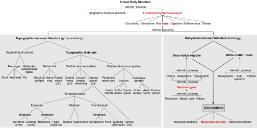
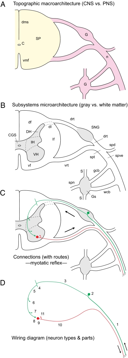
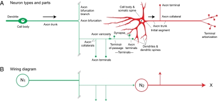
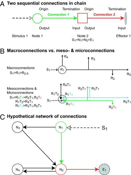
The nervous system is a biological computer integrating the body's reflex and voluntary environmental interactions (behavior) with a relatively constant internal state (homeostasis)-- promoting survival of the individual and species. The wiring diagram of the nervous system's structural connectivity provides an obligatory foundational model for understanding functional localization at molecular, cellular, systems, and behavioral organization levels. This paper provides a high-level, downwardly extendible, conceptual framework--like a compass and map--for describing and exploring in neuroinformatics systems (such as our Brain Architecture Knowledge Management System) the structural architecture of the nervous system's basic wiring diagram. For this, the Foundational Model of Connectivity's universe of discourse is the structural architecture of nervous system connectivity in all animals at all resolutions, and the model includes two key elements--a set of basic principles and an internally consistent set of concepts (defined vocabulary of standard terms)--arranged in an explicitly defined schema (set of relationships between concepts) allowing automatic inferences. In addition, rules and procedures for creating and modifying the foundational model are considered. Controlled vocabularies with broad community support typically are managed by standing committees of experts that create and refine boundary conditions, and a set of rules that are available on the Web.


Conflict of interest statement

The authors declare no conflict of interest.

Figures

Fig. 1.
Fig. 1.
General FMC schema. The nervous system of all animals is described in two complementary, alternate ways: topographic macroarchitecture (gross anatomy) and subsystems microarchitecture (histology). All schema concepts are defined in a controlled vocabulary (see thesaurus in SI Text). Structural connectivity is described primarily in terms of regions (including neuron types, parts, and molecules) and tracts, with the mesoconnectional level (based on neuron types) being most informative.
Fig. 2.
Fig. 2.
General description of symmetry and positional information. (A) Nerve net (red) in animal (hydra) with radial symmetry, and two orthogonal axes (rostrocaudal, oral–aboral, or longitudinal; transverse) and planes of section (longitudinal, transverse). The relative position along tentacles is indicated. (B) Bilaterally symmetrical animals have three cardinal axes and three orthogonal planes of section, shown for an idealized chordate body plan with central nervous system dorsal to notochord and digestive system ventral to it. CNS topographic divisions are color-coded to match Fig. 3B. C, caudal; D, dorsal; L, lateral; Lt, left; M, medial; R, rostral; Rt, right; V, ventral. B (Top) is adapted from figure 1 in ref. . [Reprinted from The Vertebrae Body, A.S. Romer, page 3, Copyright (1962).]
Fig. 3.
Fig. 3.
Metazoan conceptual longitudinal axis is quite variable in embryos and adults. (A) Adult human in comparative anatomical position for easy comparison with other vertebrates (Fig. 2B) and application of the same positional descriptors. Also note the difference between topographic and systems body descriptions (Fig. 1). The former includes head (h), neck (n), trunk (t), upper limb (ul), and lower limb (ll) divisions; an example of the latter is the CNS (color-coded as in B and Fig. 2B) extending across body divisions. [Reprinted from Basic Neurology, J.P. Schade & D.H. Ford, page 15, Copyright (1965).] (B) Neural tube of a 4-wk-old human embryo (dashed line is longitudinal–rostrocaudal axis). The top is the right half of the neural tube with topographic divisions (Fig. 1 Left) color-coded to match a conceptualized straightened neural tube (bottom half) in frontal section (Fig. 2B). C, caudal; D, dorsal; EB, endbrain; FB, forebrain; HB, hindbrain; IB, interbrain; MB, midbrain; MY, medulla (afterbrain); R, rostral; RB, rhombicbrain; SP, spinal cord; V, ventral. A is adapted with permission from ref. ; the photo in B is adapted from ref. .
Fig. 4.
Fig. 4.
Comparing vertebrate nervous system topographic macroarchitecture and subsystems microarchitecture (Fig. 1). (A) Magnificent Vesalius drawing (13) shows the adult human nervous system dissected free from the body. Note the CNS location down the median plane with the spinal column intact around the spinal cord to strengthen the preparation. The CNS is basically in the position of Fig. 3A—with the brain rotated back to show its base. The PNS shows spinal nerves to limbs and trunk, which outline the body, and stubs of cranial nerves cut after leaving the brain base. For clarity, he placed autonomic nerves in a separate figure. (B) Seminal Cajal drawing (43) shows elementary network model of nervous system organization based on neuron doctrine and the functional polarity hypothesis. The former stated that the basic unit of nervous system organization is the neuron, a cell type usually interacting with other cells by contact or contiguity, not continuity; the latter stated that in typical neurons, information conducts from dendrites and the cell body (input side) to the axon (output side). This basic hypothesis allowed information flow prediction (arrows) in neural networks based on individual neuron shape. A, cerebral cortex; a, pyramidal cell > motoneuron axon; B, spinal cord; b, motoneuron; C, motoneuron axon branches > muscle fibers; c, spinal nerve ganglion cell axon; D, spinal nerve ganglion; D′, skin; d, spinal nerve ganglion cell dendrite; e, sensory axon bifurcation branch; f, somatosensory brainstem relay; g, brainstem somatosensory > cortex axon terminals.
Fig. 5.
Fig. 5.
Deconstruction of vertebrate topographic macroarchitecture and subsystems microarchitecture organization (Fig. 4B). (A) Gross anatomy level distinguishes CNS (yellow) and PNS (pink) divisions with spinal cord (SP), and nerves (n) and ganglia (G), respectively. (B) Histology level distinguishes regions (gray) and tracts (white). (C) Connection level describes cell-level synaptic interactions between different regions (macroconnections), neuron types (mesoconnections), or individual neurons (microconnections, here), including route information. The simplest mammalian spinal reflex (monosynaptic myotatic) is illustrated; arrows indicate information flow. (D) Wiring diagram level shows connections at abstract level of neuron types and parts, and routes. Connectomes and basic plans are further abstractions. C, central canal; CGS, spinal central gray; df, dorsal funiculus; dh, dorsal horn; dl, dorsolateral fascicle; dms, dorsal median septum; drt, dorsal root; G, ganglion; gcb, gray communicating branch; Gs, sympathetic ganglion; IH, intermediate horn; lf, lateral funiculus; n, nerve; S, sympathetic trunk; SNG, spinal nerve ganglion; SP, spinal cord; spd, spinal nerve dorsal branch; spn, splanchnic nerve; spt, spinal nerve trunk; spve, spinal nerve ventral branch; vf, ventral funiculus; VH, ventral horn; vmf, ventral median fissure; vrt, ventral root; wcb, white communicating branch. 1, dendrite of 2; 2, pseudopolar spinal nerve ganglion cell body (green); 3, axon of 2; 4, bifurcation branch of 3; 5, axon collateral of 4; 6, collateral of 5 to dorsal nucleus; 7, collateral of 5 to VH inhibitory interneurons; 8, axon terminals of 5 on 9; 9, α-motoneuron innervating extensor muscle (red); 10, axon of 9; 11, local axon collateral of 10.
Fig. 6.
Fig. 6.
Key neuron parts to describe connections with an example of monosynaptic sensory-motor reflex (Fig. 5). (A) Bipolar sensory neuron (green) and multipolar motoneuron (red) parts shown with information flow direction indicated (arrows). Fig. S4 has other configurations. See thesaurus (SI Text) for part definitions. (B) Wiring diagram schematizing connections in A. Two nodes (N1, N2) are shown and could represent regions (macroconnections), neuron types (mesoconnections), or individual neurons, as in A (microconnections).
Fig. 7.
Fig. 7.
Concepts for describing connections. (A) Basic terms for describing axonal connections. (B) Difference between macroconnections, where regions (R) are black boxes, and meso- and microconnections, where specific connections are made between neuron types (T) and individual neurons, respectively, within regions. A simple self-evident notation for describing relationships in A and B is given. (C) A hypothetical network of four nodes (N1–4), a stimulus (S1), and an effector (E1); note closed chain (circuit) between N2 and N4.

Similar articles

Cited by

References

    1. Tiedemann F. Anatomy of the Foetal Brain. Edinburgh: Carfrae; 1826. p. 2.
    1. Meadows DM. Thinking in Systems. White River Junction, VT: Chelsea Green; 2008. p. 1.
    1. Watson JD, Crick FHC. Molecular structure of nucleic acids: A structure for deoxyribose nucleic acid. Nature. 1953;171:737–738. - PubMed
    1. Pauling L, Corey RB. A proposed structure for the nucleic acids. Proc Natl Acad Sci USA. 1953;39:84–97. - PMC - PubMed
    1. Bota M, Dong H-W, Swanson LW. From gene networks to brain networks. Nat Neurosci. 2003;6:795–799. - PubMed

Publication types

LinkOut - more resources