

A static multi-slit collimator system for scatter reduction in cone-beam CT
- PMID: 21081885
- PMCID: PMC5720400
- DOI: 10.1120/jacmp.v11i4.3269
A static multi-slit collimator system for scatter reduction in cone-beam CT
Abstract
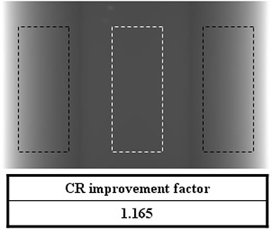
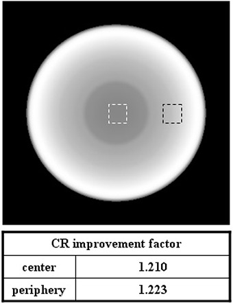
A multiple-slit collimator (MSC) design was introduced for scatter reduction in cone-beam computed tomography (CBCT). Unlike most other collimators, the open and closed septa of the proposed MSC are placed in an equi-angular interval on a circular track of the central sagittal plane. Therefore, one gantry rotation provides only the half of necessary dataset and two gantry rotations are needed to obtain full information. During the first gantry rotation, the MSC position relative to the source is fixed. For the second rotation, the MSC is rotated by the equi-angle interval. We assume signals under the closed septa are totally attributed to scatter radiation. Then, scatter contributions under open septa are determined by interpolating them.Monte Carlo (MC) simulations for two virtual phantoms (one with a simple geometry and the other with two heterogeneities simulating the bone and the lung) were performed to evaluate the effectiveness of the system. Using the method developed, we could obtain images with significant scatter reduction. Contrast ratio (CR) improvement factors were 1.165 in a 2D projection view, and 1.210 and 1.223 at the central and peripheral slice of the reconstructed CBCT image of the simple geometry phantom.This preliminary study demonstrated that the proposed MSC, together with the imaging process technique, had a great potential to reduce scatter contribution in CBCT. Further studies will be performed to investigate the effect of various factors, such as reducing the detector size, increasing the number of history of MC simulation, and including many structures with different densities.
Figures


Similar articles
-
Combining scatter reduction and correction to improve image quality in cone-beam computed tomography (CBCT).Med Phys. 2010 Nov;37(11):5634-44. doi: 10.1118/1.3497272. Med Phys. 2010. PMID: 21158275
-
Cone-beam breast computed tomography with a displaced flat panel detector array.Med Phys. 2012 May;39(5):2805-19. doi: 10.1118/1.4704641. Med Phys. 2012. PMID: 22559652
-
Panoramic cone beam computed tomography.Med Phys. 2012 May;39(5):2930-46. doi: 10.1118/1.4704640. Med Phys. 2012. PMID: 22559664
-
Simulated scatter performance of an inverse-geometry dedicated breast CT system.Med Phys. 2009 Mar;36(3):788-96. doi: 10.1118/1.3077165. Med Phys. 2009. PMID: 19378739
-
Patient-specific scatter correction in clinical cone beam computed tomography imaging made possible by the combination of Monte Carlo simulations and a ray tracing algorithm.Acta Oncol. 2013 Oct;52(7):1477-83. doi: 10.3109/0284186X.2013.813641. Epub 2013 Jul 23. Acta Oncol. 2013. PMID: 23879648
References
-
- Jaffray DA, Siewerdsen JH, Wong JW, Martinez AA. Flat‐panel cone‐beam computed tomography for image‐guided radiation therapy. Int J Radiat Oncol Biol Phys. 2002;53(5):1337–49. - PubMed
-
- Hawkins MA, Brock KK, Eccles C, Moseley D, Jaffray D, Dawson LA. Assessment of residual error in liver position using kV cone‐beam computed tomography for liver cancer high‐precision radiation therapy. Int J Radiat Oncol Biol Phys. 2006;66(2):610–19. - PubMed
-
- Langen KM, Meeks SL, Poole DO, et al. The use of megavoltage CT (MVCT) images for dose recomputations. Phys Med Biol. 2005;50(18):4259–76. - PubMed
-
- Samant SS, Xia J, Muyan‐Özçelik P, Owens JD. High performance computing for deformable image registration: towards a new paradigm in adaptive radiotherapy. Med Phys. 2008;35(8):3546–53. - PubMed
Publication types
MeSH terms
LinkOut - more resources
Full Text Sources
