. 2010 Dec 28;4(12):7253-66.
doi: 10.1021/nn1021346. Epub 2010 Nov 17.

Quantum dot DNA bioconjugates: attachment chemistry strongly influences the resulting composite architecture

Affiliations

Quantum dot DNA bioconjugates: attachment chemistry strongly influences the resulting composite architecture

Kelly Boeneman et al. ACS Nano. .

Abstract

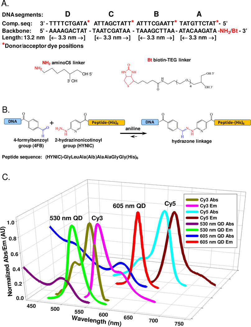
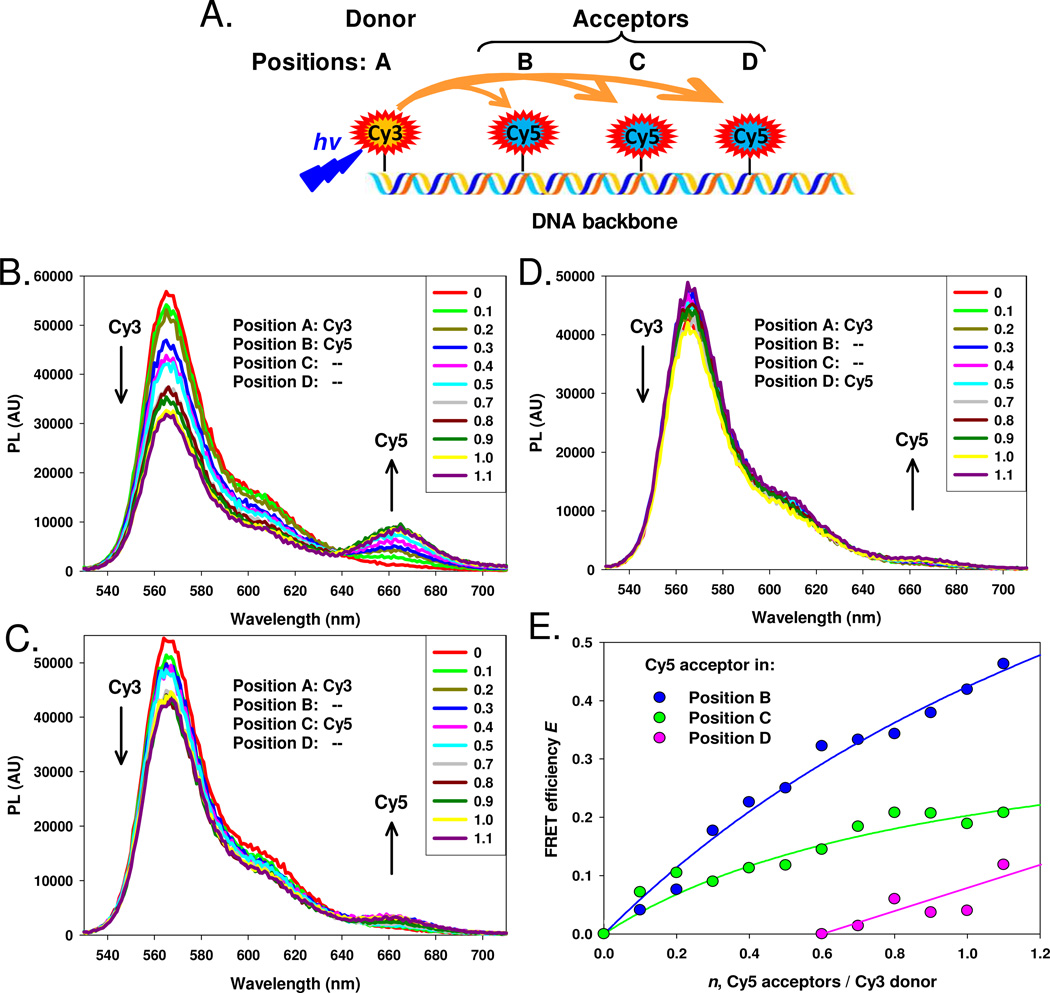
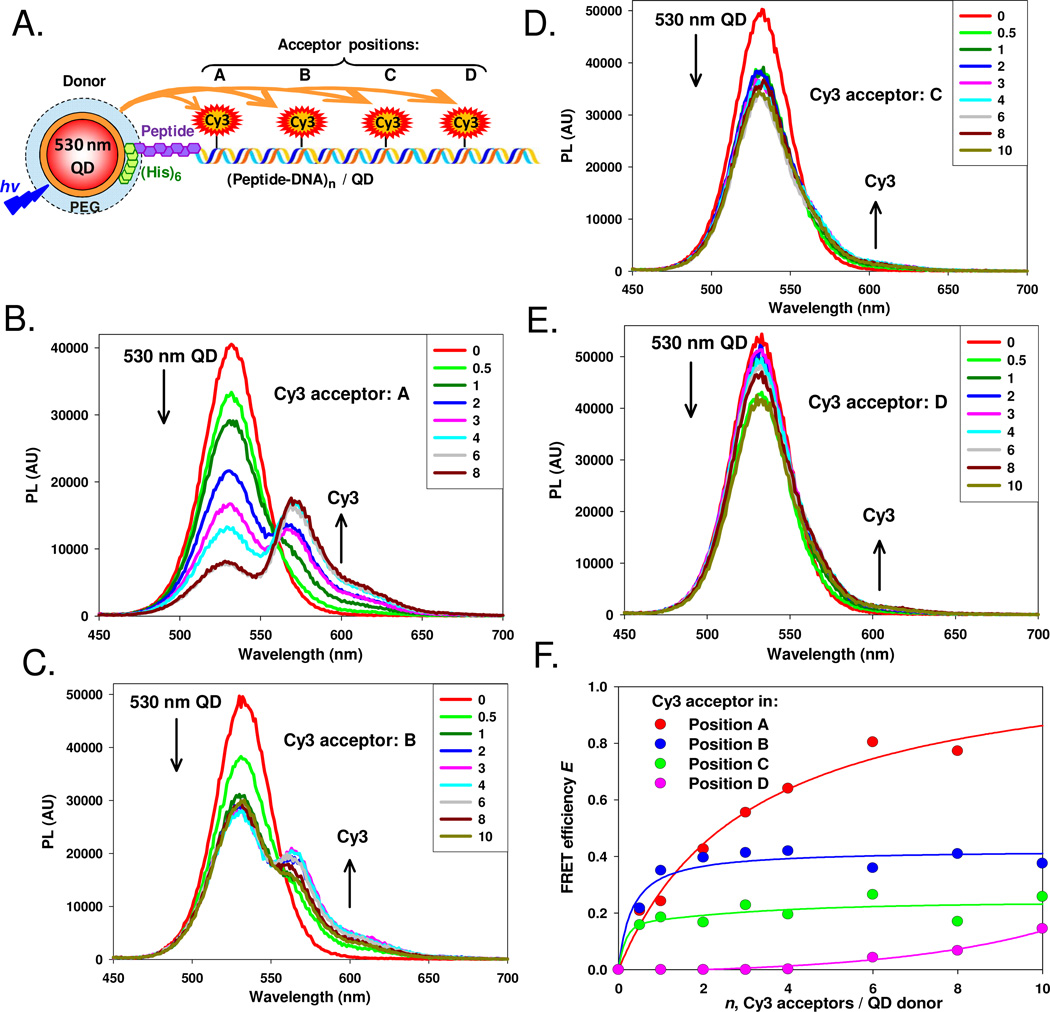
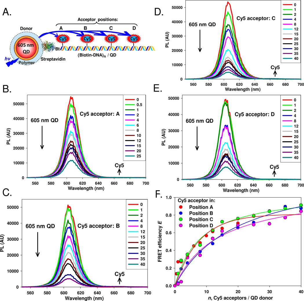
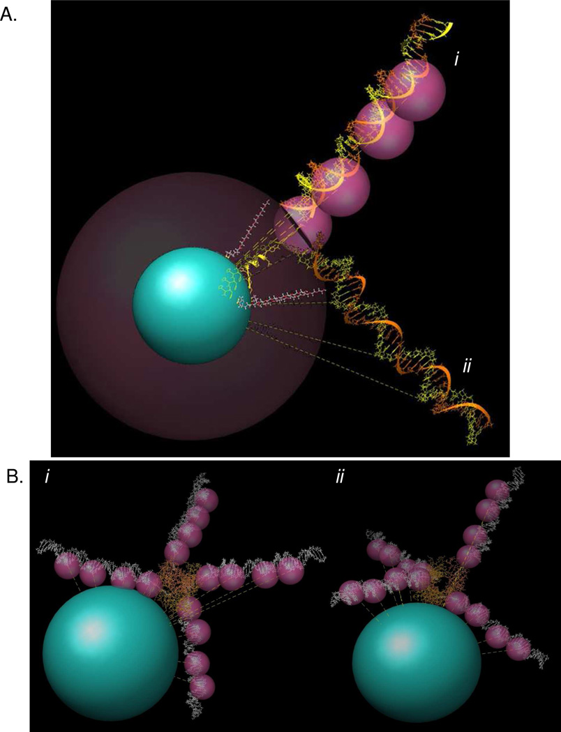
The unique properties provided by hybrid semiconductor quantum dot (QD) bioconjugates continue to stimulate interest for many applications ranging from biosensing to energy harvesting. Understanding both the structure and function of these composite materials is an important component in their development. Here, we compare the architecture that results from using two common self-assembly chemistries to attach DNA to QDs. DNA modified to display either a terminal biotin or an oligohistidine peptidyl sequence was assembled to streptavidin/amphiphilic polymer- or PEG-functionalized QDs, respectively. A series of complementary acceptor dye-labeled DNA were hybridized to different positions on the DNA in each QD configuration and the separation distances between the QD donor and each dye-acceptor probed with Förster resonance energy transfer (FRET). The polyhistidine self-assembly yielded QD-DNA bioconjugates where predicted and experimental separation distances matched reasonably well. Although displaying efficient FRET, data from QD-DNA bioconjugates assembled using biotin-streptavidin chemistry did not match any predicted separation distances. Modeling based upon known QD and DNA structures along with the linkage chemistry and FRET-derived distances was used to simulate each QD-DNA structure and provide insight into the underlying architecture. Although displaying some rotational freedom, the DNA modified with the polyhistidine assembles to the QD with its structure extended out from the QD-PEG surface as predicted. In contrast, the random orientation of streptavidin on the QD surface resulted in DNA with a wide variety of possible orientations relative to the QD which cannot be controlled during assembly. These results suggest that if a particular QD biocomposite structure is desired, for example, random versus oriented, the type of bioconjugation chemistry utilized will be a key influencing factor.


Figures

Figure 1
Figure 1. DNA sequences, chemoselective ligation and spectral overlap
(A) Sequences of the DNA backbone with a 3’ amino or biotin functionalization and the complementary DNA segments (A–D) showing donor/acceptor labeling sites at the 5’ end of each. (B) Aniline catalyzed hydrazone ligation between the aldehyde (blue) of the 4FB group and the peptidyl HYNIC group (red) used to link DNA to the (His)6-peptide. (C) Plot showing the spectral overlap of the fluorophore donor-acceptor species used; Cy3-Cy5, 530 nm QD-Cy3 and 605 nm QD-Cy5.
Figure 2
Figure 2. Construct 1: dye-based DNA assembly
(A) Schematic of the nanoconstruct comprised of a Cy3 donor at position A with a Cy5 acceptor placed at position B, C or D. When a position is not used, the equivalent unlabeled spacer is hybridized in that location. (B–D) PL spectra of Cy3-donor in position A with increasing molar ratios of Cy5-labeled acceptor DNA placed in positions B, C or D, respectively. (E) FRET efficiency E for each acceptor position versus acceptor valence. Lines of best fit added.
Figure 3
Figure 3. Construct 2: (His)6-peptide-DNA QD assembly
(A) Schematic of the nanoconstruct comprised of a 530 nm QD donor self-assembled with (His)6-labeled peptide-DNA and Cy3 acceptors placed at positions A–D. When a position is not used, the equivalent unlabeled spacer is hybridized in that location. (B–E) PL spectra of QD donors self-assembled with increasing molar ratios of Cy3 labeled DNA in positions A–D, respectively. (F) Plot of FRET efficiency E for each acceptor position versus acceptor valence. Lines of best fit added.
Figure 4
Figure 4. Construct 3: Biotin-DNA streptavidin QD assembly
(A) Schematic of the nanoconstruct comprised of a streptavidin-functionalized 605 nm QD bound to the biotin labeled 5’ end of the DNA backbone hybridized with Cy5 acceptor DNA at positions A–D. When a position is not used, unlabeled spacer DNA is hybridized in that location. (B–E) PL spectra of 605 nm QD donors conjugated to increasing molar ratios of Cy5 labeled DNA in positions A–D, respectively. (F) Plot of FRET efficiency E for each acceptor position versus acceptor valence. Lines of best fit added.
Figure 5
Figure 5. Modeling of QD-DNA structures
(A) (His)6-peptide-DNA bound to 530 nm QDs. The QD is shown as the central blue sphere with a radius of 27–28 Å. The DHLA-PEG ligand is indicated by the crimson halo with an estimated extension of 30 Å utilized here for modeling purposes. DHLA-PEG ligands in an energy minimized conformation are shown within the crimson sphere. The (His)6-portion of the peptide is shown with a yellow ribbon attached to the HYNIC linker. Individual DNA strands within the dsDNA structure are shown in orange and yellow. The rotational extension of the dye molecules are shown by the magenta spheres. Two possible orientations of the DNA relative to the QDs are shown. (i) DNA extending linearly outward from the QD surface and (ii) DNA adjusted for the measured r values. Dashed lines represent expected or measured distances for each configuration. (B) Biotinylated-DNA bound to the 605 nm streptavidin QDs. The QD-core/shell/polymer is simulated by a blue sphere of ~75 Å radius according to manufacturer specifications. The streptavidin is shown in orange with DNA’s (white) attached at all 4 binding sites. Fluorescent extensions of the dye molecules are shown by the magenta spheres. Two possible orientations of the DNA relative to the QDs are shown and are derived by changing the orientation of the streptavidin relative to the QD surface. Note that regardless of orientation, several dyes at all possible acceptor sites (A–D) are always in close proximity to the QD surface.

References

    1. Gill R, Zayats M, Willner I. Semiconductor Quantum Dots for Bioanalysis. Angew. Chem. Int. Ed. 2008;47:7602–7625. - PubMed
    1. Pumera M, Sanchez S, Ichinose I, Tang J. Electrochemical Nanobiosensors. Sens. & Act. B-Chem. 2007;123:1195–1205.
    1. Cheon J, Lee JH. Synergistically Integrated Nanoparticles as Multimodal Probes for Nanobiotechnology. Acc. Chem. Res. 2008;41:1630–1640. - PubMed
    1. Medintz I. Universal Tools for Biomolecular Attachment to Surfaces. Nat. Materials. 2006;5 842-842. - PubMed
    1. Aubin-Tam ME, Hamad-Schifferli K. Structure and Function of Nanoparticle-Protein Conjugates. Biomedical Materials. 2008;3 Article # 034001. - PubMed

Publication types