. 2011 Mar;58(3):499-508.
doi: 10.1109/TBME.2010.2093896. Epub 2010 Nov 22.

Intraoperative brain shift compensation: accounting for dural septa

Affiliations

Intraoperative brain shift compensation: accounting for dural septa

Ishita Chen et al. IEEE Trans Biomed Eng. 2011 Mar.

Abstract

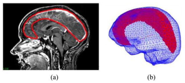
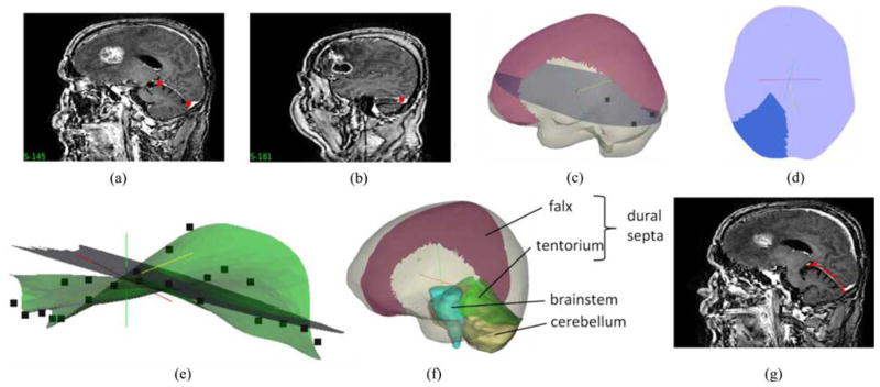
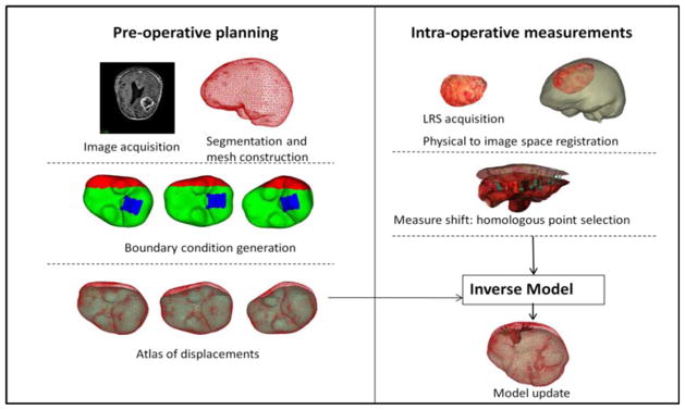
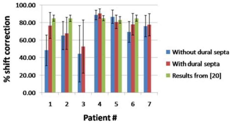
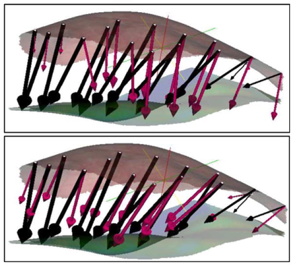
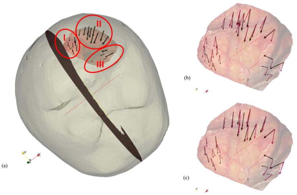
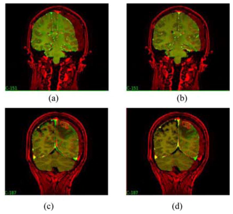
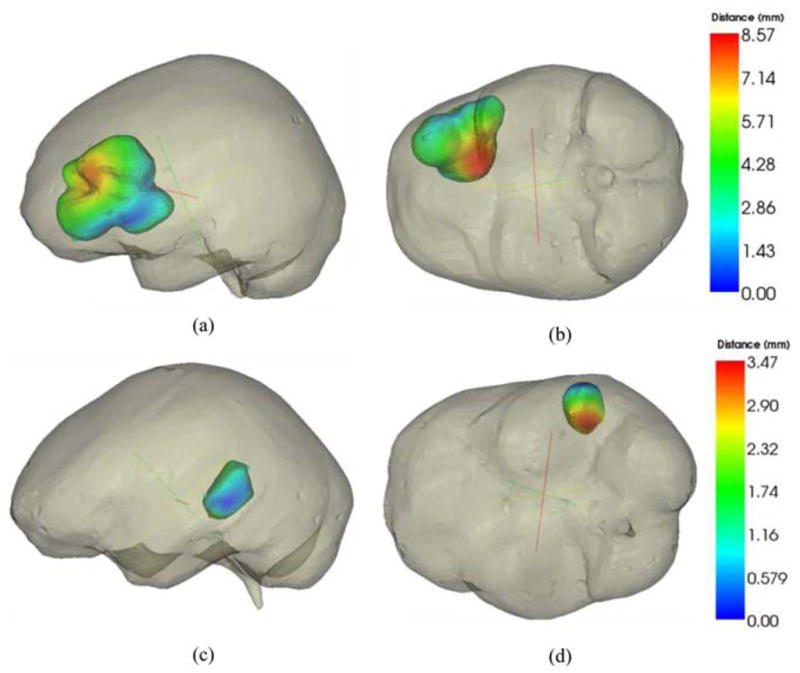
Biomechanical models that describe soft tissue deformation provide a relatively inexpensive way to correct registration errors in image-guided neurosurgical systems caused by nonrigid brain shift. Quantifying the factors that cause this deformation to sufficient precision is a challenging task. To circumvent this difficulty, atlas-based methods have been developed recently that allow for uncertainty, yet still capture the first-order effects associated with deformation. The inverse solution is driven by sparse intraoperative surface measurements, which could bias the reconstruction and affect the subsurface accuracy of the model prediction. Studies using intraoperative MR have shown that the deformation in the midline, tentorium, and contralateral hemisphere is relatively small. The dural septa act as rigid membranes supporting the brain parenchyma and compartmentalizing the brain. Accounting for these structures in models may be an important key to improving subsurface shift accuracy. A novel method to segment the tentorium cerebelli will be described, along with the procedure for modeling the dural septa. Results in seven clinical cases show a qualitative improvement in subsurface shift accuracy making the predicted deformation more congruous with previous observations in the literature. The results also suggest a considerably more important role for hyperosmotic drug modeling for the intraoperative shift correction environment.


Figures

Fig. 1
Fig. 1
(Left) LRS performing a scan during surgery. (Right) Scanner mounted on arm being tracked by the camera on right.
Fig. 2
Fig. 2
Falx segmentation procedure. (a) Manual periphery drawn around falx on gadolinium-enhanced MRI and (b) segmented falx overlaid with the mesh.
Fig. 3
Fig. 3
Procedure for tentorium segmentation. (a) and (b) Selection of three points used for clipping a plane in the mesh, (c) clipped plane (with those three points) overlaid with the mesh and the falx, (d) clipped plane segmented into an approximate tentorium shaped structure, and (e) segmented plane with the final tentorium surface created by morphing the plane in (d) using a thin plate spline algorithm. Points on the surface are the target points used to drive the thin plate spline algorithm. (f) Mesh overlaid with the segmented falx and the tentorium surfaces. Segmented brainstem (in blue) and cerebellum (in yellow) shown for reference were not modeled separately. (g) Saggital MRI slices overlaid with the red points of the tentorium surface. Good overlap of the points and the hyperintense region indicate the quality of segmentation.
Fig. 4
Fig. 4
Schematic showing the overall procedure for model updated image-guided neurosurgery. Workflow is broadly divided into preoperative and intraoperative phases. Most time intensive steps are done in the preoperative phase, i.e., image segmentation and mesh construction. Boundary conditions for each deformation type and generation of model solutions to form the atlas are also done preoperatively. Some representative displacement boundary conditions are shown—with blue region being the fixed brainstem, red represents the stress free region, and green the slippage boundary conditions. Dural septa (not shown in the figure) are included in the model by assigning them the slippage boundary condition. Intraoperative phase consists of sparse data collection (laser range scans), registration of those scans to image space and obtaining measured shift through homologous points on the pre- and postresection scans. In the last step, those measurements are used to fit the displacement atlas using an inverse model to obtain the final model updated results.
Fig. 5
Fig. 5
Shift recoveries for seven patient cases for meshes with and without dural septa. Also shown are the shift recoveries obtained for the corresponding pre- and postoperative MR data reported in [20]. That analysis was unavailable for patients 3 and 7.
Fig. 6
Fig. 6
Measured shift vectors (black) and predicted shift vectors (magenta) for the concatenated atlas using the method of constraints for above: model without dural septa and below: model with dural septa. Vectors are overlaid with the preresection (top) and postresection (bottom) LRS surfaces.
Fig. 7
Fig. 7
(a) Mesh surface overlaid with the postresection LRS and measurement vectors. The homologous points are divided into three different regions: I, II, and III. Preresection LRS overlaid with the measurement vectors and the predicted vectors for the (b) model without dural septa and (c) model with dural septa for the concatenated atlas.
Fig. 8
Fig. 8
Preoperative image (red) overlaid with model-deformed image (green) for the model without dural septa, (a) and (c), and the model with dural septa, (b) and (d). (a) and (b) Results for Patient 1, and (c) and (d) results for Patient 3.
Fig. 9
Fig. 9
Color-coded vector difference in predicted displacements for model with and without the dural septa. Top row figures are representation for Patient 2 and lower row is representation for Patient 4. Two different camera angles have been shown for each patient for better visual clarity.
Fig. 10
Fig. 10
Distribution of weighting coefficients for the gravity and mannitol solutions for patients 1, 4, and 7 obtained by optimizing the least-squared error in intraoperative data.

References

    1. Nimsky C, Ganslandt O, Cerny S, Hastreiter P, Greiner G, Fahlbusch R. Quantification of, visualization of, and compensation for brain shift using intraoperative magnetic resonance imaging. Neurosurgery. 2000 Nov;47(5):1070–1079. - PubMed
    1. Roberts DW, Hartov A, Kennedy FE, Miga MI, Paulsen KD. Intraoperative brain shift and deformation: A quantitative analysis of cortical displacement in 28 cases. Neurosurgery. 1998 Oct;43(4):749–758. - PubMed
    1. Kelly PJ. Intraoperative brain shift and deformation: A quantitative analysis of cortical displacement in 28 cases— Comment. Neurosurgery. 1998 Oct;43(4):759–759. - PubMed
    1. Butler WE, Piaggio CM, Constantinou C, Nikalson L, Gonzales RG, Cosgrove GR, Zervas NT. A mobile computed tomographic scanner with intraoperative and intensive care unit applications. Neurosurgery. 1998;88(4):1304–1310. - PubMed
    1. Letteboer MMJ, Willems PWA, Viergever MA, Niessen WJ. Brain shift estimation in image-guided neurosurgery using 3-D ultrasound. IEEE Trans Biomed Eng. 2005 Feb;52(2):268–276. - PubMed

Publication types