. 2011 Feb;208(2):291-7.
doi: 10.1016/j.jmr.2010.11.004. Epub 2010 Dec 4.

A radiofrequency coil configuration for imaging the human vertebral column at 7 T

Affiliations

A radiofrequency coil configuration for imaging the human vertebral column at 7 T

M Vossen et al. J Magn Reson. 2011 Feb.

Abstract

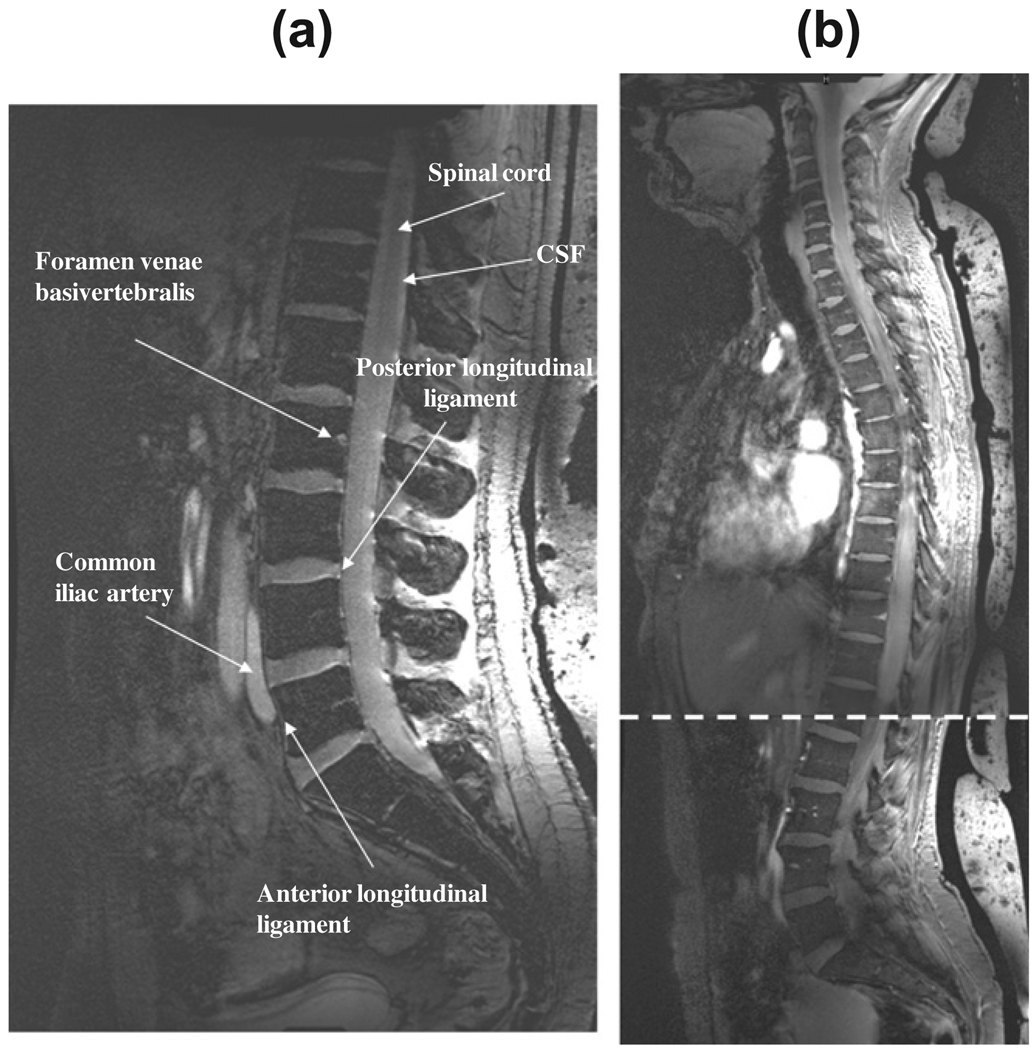
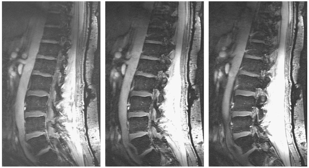
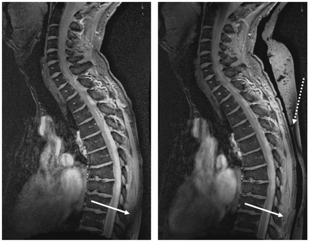
We describe the design and testing of a quadrature transmit, eight-channel receive array RF coil configuration for the acquisition of images of the entire human spinal column at 7 T. Imaging parameters were selected to enable data acquisition in a clinically relevant scan time. Large field-of-view (FOV) scanning enabled sagittal imaging of the spine in two or three-stations, depending upon the height of the volunteer, with a total scan time of between 10 and 15 min. A total of 10 volunteers have been scanned, with results presented for the three subjects spanning the range of heights and weights, namely one female (1.6 m, 50 kg), one average male (1.8 m, 70 kg), and one large male (1.9 m, 100 kg).


Figures

Fig. 1
Fig. 1
(top) Schematic drawing of the eight-element receive array with relevant dimensions and capacitor values. The eight-coils are grounded together as close to the coil as possible, and then again at a distance approximately one-quarter wavelength down the identical-length RG-58 coaxial-cables. (bottom) Measured noise correlation matrix for the eight-element array loaded with a volunteer.
Fig. 2
Fig. 2
Results from electromagnetic simulations of (top row) the rotating B1+ component of the transmit RF field, and (bottom row) the voxel-based SAR values. (a), (c), (e), (g), (i) and (k) show results with the quadrature transmit coil place anterior to the subject, with (b), (d), (f), (h), (j) and (l) with the coil placed in a posterior position. The values are plotted on a logarithmic scale. For the B1+ maps 0 dB corresponds to a value of 4.35 µT per square root Watts of input power, and for the SAR maps the corresponding value is 1.05 W/kg per Watt of input power.
Fig. 3
Fig. 3
Sagittal images through the cervical spine of a female (a), and male (b, c, two different slice positions) volunteers with the quadrature transmit coil positioned centrally on the chest with the upper edge placed against the chin. Despite the residual effects of cardiac motion fine structures such as the feeding vessels (foramen venae basivertebralis) can be discerned as areas of high intensity. There is good contrast between the CSF and the nerve fiber tracks and a relatively uniform signal intensity from the posterior and anterior sections of the vertebral column. Signal from the dielectric bag behind the back can be seen at the far right of the images. Female height/weight 1.7 m, 58 kg: male height/weight 1.8 m, 70 kg.
Fig. 4
Fig. 4
Zoomed images of two collapsed vertebrae from Fig. 2b. Cortical irregularity of the endplates can be seen (thin arrows), consistent with osteochondrosis. The inter-vertebral disks show inhomogeneities (thick arrows) which could be based on califications in the disk or, alternatively, degeneration.
Fig. 5
Fig. 5
(a) A mid-sagittal image of the lumbar spine acquired from a patient, height 1.9 m, who weighted over 100 kg. (b) Two mid-sagittal slices of a female volunteer (height 1.7 m, 50 kg weight) which are acquired at two different positions of the patient table and stitched together at the overlap point indicated by the dotted line. No intensity correction or image smoothing has been applied to either image.
Fig. 6
Fig. 6
Three adjacent sagittal slices from a 14-slice data set with improved left/right coverage of 6 cm, and a reduced number of signal averages (four), while maintaining the same total data acquisition time as for the other images.
Fig. 7
Fig. 7
Illustration of the effects of high dielectric material on the image quality. (left) Without bag and (right) with bag. Without the bag an area of low signal intensity caused by partial destructive interference of the RF field occurs within the patient as shown by the white arrow. With the addition of the bag, this effect is removed to a location within the dielectric material itself (dotted arrow).

References

    1. Shapiro MD. MR imaging of the spine at 3T. Magn. Reson. Imaging Clin. North Am. 2006;14:97–108. - PubMed
    1. Mosher TJ. Musculoskeletal imaging at 3T: current techniques and future applications. Magn. Reson. Imaging Clin. North Am. 2006;14:63–76. - PubMed
    1. Banerjee S, Krug R, Carballido-Gamio J, Kelley DA, Xu D, Vigneron DB, Majumdar S. Rapid in vivo musculoskeletal MR with parallel imaging at 7T. Magn. Reson. Med. 2008;59:655–660. - PubMed
    1. Krug R, Stehling C, Kelley DAC, Majumdar S, Link TM. Imaging of the musculoskeletal system in vivo using ultra-high field magnetic resonance at 7 T. Invest. Radiol. 2009;44:613–618. - PubMed
    1. Krug R, Carballido-Gamio J, Banerjee S, Burghardt AJ, Link TM, Majumdar S. In vivo ultra-high-field magnetic resonance imaging of trabecular bone microarchitecture at 7 T. J. Magn. Reson. Imaging. 2008;27:854–859. - PubMed

Publication types

LinkOut - more resources