. 2011 May;14(4):227-36.
doi: 10.2174/138620711795222455.

Fabricating gradient hydrogel scaffolds for 3D cell culture

Affiliations

Fabricating gradient hydrogel scaffolds for 3D cell culture

Kaushik Chatterjee et al. Comb Chem High Throughput Screen. 2011 May.

Abstract

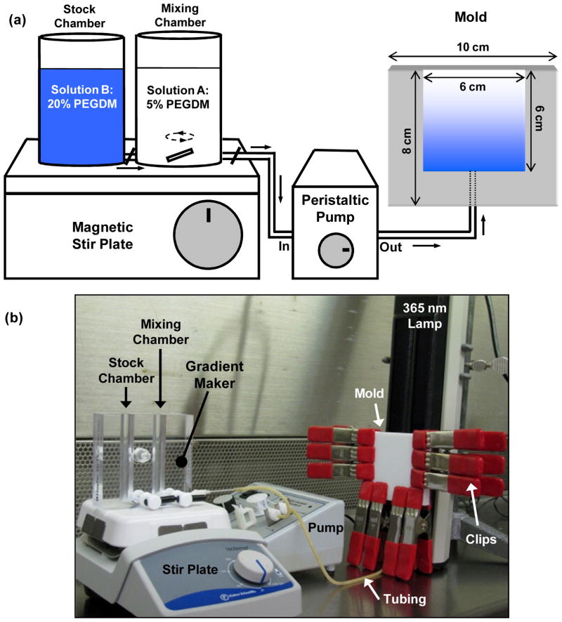
Optimizing cell-material interactions is critical for maximizing regeneration in tissue engineering. Combinatorial and high-throughput (CHT) methods can be used to systematically screen tissue scaffolds to identify optimal biomaterial properties. Previous CHT platforms in tissue engineering have involved a two-dimensional (2D) cell culture format where cells were cultured on material surfaces. However, these platforms are inadequate to predict cellular response in a three-dimensional (3D) tissue scaffold. We have developed a simple CHT platform to screen cell-material interactions in 3D culture format that can be applied to screen hydrogel scaffolds. Herein we provide detailed instructions on a method to prepare gradients in elastic modulus of photopolymerizable hydrogels.


Conflict of interest statement

CONFLICT OF INTEREST

The authors have no conflict of interests to declare.

Figures

Fig. 1
Fig. 1
(a) Schematic illustration of the combinatorial platform used to prepare hydrogel gradient scaffolds. The output of the gradient maker is pumped in to a single-entry bottom-filling vertical mold, wherein it is cured using a 365 nm lamp. (b) Photograph of the sterilized equipment arranged in a cell culture hood for aseptic gradient fabrication.
Fig. 2
Fig. 2
Disassembled parts and equipment for making hydrogel scaffold gradients. (a) Photograph of the gradient maker is shown with a needle, tubing and a magnetic stir bar that is added to the mixing chamber. (b) Disassembled mold showing a Teflon sheet machined to create a mold that is clipped between a glass slide and a Teflon block. A needle is inserted through the drilled port at the bottom of the mold. (c) A wide spackling knife (8 cm wide) is useful to handle the gradient samples.
Fig. 3
Fig. 3
Trypan blue can be added to the stock chamber solution in the gradient maker to visualize and confirm gradient formation. (a) A few drops of Trypan blue (0.01% by mass) was added to the 20% PEGDM pre-polymer solution in the stock chamber (with 5% PEGDM in the mixing chamber). In order to check linearity of the gradient maker effluent, the effluent was collected drop-wise in a 96-well plate. (b) Plot of absorbance at 600 nm measured for the different fractions collected in the 96-well plate in (a). (c) Image of the mold, as observed through the glass slide, filled with the output of the gradient maker wherein. Dashed lines indicate how the cured slab of gel (6 cm × 6 cm × 3 mm) is cut with a razor into six gradient scaffolds of 6 cm × 1 cm × 3 mm each. (d) Plot of compressive elastic moduli measured at different positions along the gradient hydrogel.
Fig. 4
Fig. 4
Experimental design for mechanical and biological characterization of gradient samples. Each gradient sample (6 cm × 1 cm × 3 mm) is cut in to six segments (1 cm × 1 cm × 3 mm). To assay the cell state in each gel segment, the segments are cut into five equal sections (1 cm × 2 mm × 3 mm) for use in the five assays indicated.
Fig. 5
Fig. 5
Images of cell response after encapsulation within hydrogel gradients. (a, b) Epi-fluorescence images of cells stained with the live (a) and the dead (b) stains at the soft end (≈ 10 kPa) of the gradient 1 d after encapsulation. (c) Phase contrast images of cells in soft end (≈ 10 kPa) of hydrogel gradients after 1 d. Spherical objects are cells. (d) Phase contrast micrographs of mineral deposits at the stiff end (≈ 300 kPa) of the gradient stained with Alizarin red S after 42 d. Dark spots are indicative of mineral deposits. Scale bar in (a) applies to (a–d) and equals 0.1 mm. (e) Photograph of gradient hydrogel after 42 d culture. Note that the hydrogel appears white at the stiff end (high modulus) due to the presence of large amounts of mineral deposits. The mineralization occurs in normal medium without osteogenic differentiation supplements.

References

    1. Lysaght MJ, Jaklenec A, Deweerd E. Great expectations: Private sector activity in tissue engineering, regenerative medicine, and stem cell therapeutics. Tissue Eng Part A. 2008;14(2):305–315. - PubMed
    1. Inglese J, Johnson RL, Simeonov A, Xia M, Zheng W, Austin CP, Auld DS. High-throughput screening assays for the identification of chemical probes. Nat Chem Biol. 2007;3(8):466–479. - PubMed
    1. Simon CG, Yang Y, Thomas V, Dorsey SM, Morgan AW. Cell interactions with biomaterials gradients and arrays. Comb Chem High Throughput Screen. 2009;12(6):544–553. - PubMed
    1. Meredith JC, Sormana JL, Keselowsky BG, Garcia AJ, Tona A, Karim A, Amis EJ. Combinatorial characterization of cell interactions with polymer surfaces. J Biomed Mater Res Part A. 2003;66(3):483–490. - PubMed
    1. Anderson DG, Levenberg S, Langer R. Nanoliter-scale synthesis of arrayed biomaterials and application to human embryonic stem cells. Nat Biotechnol. 2004;22(7):863–866. - PubMed

Publication types

MeSH terms