. 2011 Jan 19;30(2):408-16.
doi: 10.1038/emboj.2010.322. Epub 2010 Dec 14.

Atomic model of an infectious rotavirus particle

Affiliations

Atomic model of an infectious rotavirus particle

Ethan C Settembre et al. EMBO J. .

Abstract

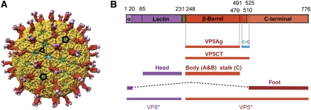
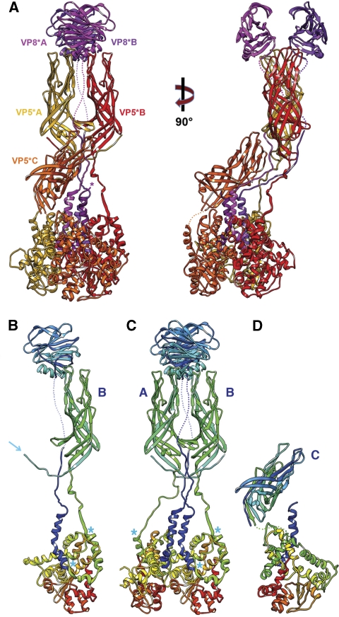
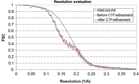
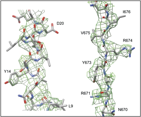
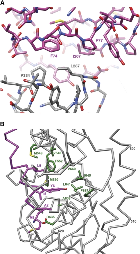
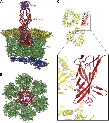
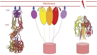
Non-enveloped viruses of different types have evolved distinct mechanisms for penetrating a cellular membrane during infection. Rotavirus penetration appears to occur by a process resembling enveloped-virus fusion: membrane distortion linked to conformational changes in a viral protein. Evidence for such a mechanism comes from crystallographic analyses of fragments of VP4, the rotavirus-penetration protein, and infectivity analyses of structure-based VP4 mutants. We describe here the structure of an infectious rotavirus particle determined by electron cryomicroscopy (cryoEM) and single-particle analysis at about 4.3 Å resolution. The cryoEM image reconstruction permits a nearly complete trace of the VP4 polypeptide chain, including the positions of most side chains. It shows how the two subfragments of VP4 (VP8(*) and VP5(*)) retain their association after proteolytic cleavage, reveals multiple structural roles for the β-barrel domain of VP5(*), and specifies interactions of VP4 with other capsid proteins. The virion model allows us to integrate structural and functional information into a coherent mechanism for rotavirus entry.


Conflict of interest statement

PRD and ECS are employees and shareholders of Novartis Vaccines and Diagnostics, Inc.

Figures

Figure 1
Figure 1
Structure of VP4 spike. (A) Overview of rotavirus TLP, in surface rendering from the cryoEM map and coordinates. VP8* is in magenta, VP5* is in red, and VP7 is in yellow. Selected icosahedral symmetry elements—two five-fold axes and a three-fold axis—are indicated by pentagons and a triangle, respectively. The VP7 trimers form a T=13 l icosahedral surface lattice, with six-coordinated positions intervening between the five-folds. There are two symmetrically distinct six-coordinated positions—VP4 spikes occupy those closer to the five-folds. Some of VP6 (green) and VP2 (blue) on the inner capsid particle can be seen through the gaps in the VP7 lattice at the six-coordinated positions not occupied by VP4 and at the five-folds. (B) Diagram of the organization of the VP4 polypeptide chain (Dormitzer et al, 2001, 2004). Tryptic cleavage generates VP8* (magenta in coloured bar) and VP5* (red), with excision of residues 232–247 (green). The segments and domains of VP8* and VP5* (α, lectin, β-barrel, c-c, C-terminal) are labelled; the β-barrel domain was called the ‘antigen domain' (VP5Ag) in some of our previous papers; the fragment generated from recombinant VP4 by successive cleavages with chymotrypsin and trypsin is called VP5CT. We have described the morphology of the spikes in the mature virion (after tryptic cleavage of VP4) as ‘head', ‘body', ‘stalk', and ‘foot'; the polypeptide-chain segments contributing to each of these structures are shown as labelled lines. The structure described in this paper reveals that the β-barrel domains of two subunits form the body and that of the third forms the stalk and that the foot includes both the segment at the N-terminus of VP8* labelled ‘α‘ and the C-terminal domain. The segment labelled ‘c-c' forms the three-chain coiled coil in the VP5CT trimer crystal structure, which probably shows the conformation of rearranged VP5* following membrane disruption (see Figure 7). Amino-acid residues at domain, segment, and fragment boundaries are designated by numbers above the coloured bar.
Figure 2
Figure 2
(A) Ribbon representation of the VP4 (=VP8*+VP5*) spike. Two orthogonal views are shown. The VP8* fragments are in magenta (at the top of the molecule on the left, VP8*A is in the foreground and VP8*B is in the background); the VP5* fragments are in yellow (chain A), red (chain B), and orange (chain C). The models for the lectin- and β-barrel domains are based on the crystallographic coordinates (1KQR and 2B4H, respectively); those of the former were docked into the density, and those of the latter, docked and adjusted as described in Results. Connections evident from the map but not strong enough to represent in the deposited coordinates are shown as dotted lines. (B) The B chain (both VP8* and VP5*), coloured in a ‘rainbow' from blue (N-terminus) to red (C-terminus). The arrow shows the N-terminus of VP5*. Blue asterisks (both here and in C, D) designate ends of the segments that will form the three-chain coiled coil in the rearranged VP5* conformation. (C) The A and B chains, coloured as in (B). Note that the N-termini of VP5* A and B cross-over to interact with the β-barrel domain of the partner subunit. This exchange is also present in the crystal structure of a VP5Ag dimer (Yoder and Dormitzer, 2006); it may stabilize the asymmetric spike conformation after trypsin cleavage. (D) The C chain, coloured as in (B).
Figure 3
Figure 3
Resolution estimation. The red curve shows the FSC calculated for the icosahedral reconstruction using the CTF parameters measured by CTFTILT, which takes into account defocus variations across the image that arise from sample tilt (Mindell and Grigorieff, 2003). The FSC shown in blue was calculated for the reconstruction after refining the defocus of individual particles using restraints (Chen et al, 2009). This reconstruction was further analysed (black curve) using the computer program RMEASURE (Sousa and Grigorieff, 2007), which represents an alternative resolution estimate, confirming the estimate based on the FSC. The small discrepancy between the RMEASURE and FSC curves at lower resolution is due to the smoothed curve implemented in RMEASURE to represent its resolution estimate.
Figure 4
Figure 4
Portions of the three-fold averaged density map of the VP4 foot, with the final model superposed. On the left is a part of the N-terminal helical region of VP8*, contoured at 1.5 σ; on the right is a strand in VP5* between residues 670 and 677, contoured at 1.0 σ.
Figure 5
Figure 5
(A) The contact between the hydrophobic loops of the VP5* β-barrel and the lectin domain of VP8*. (B) The N-terminal helix of VP8* (‘α‘ in Figure 1B) and its interactions with the C-terminal domain of VP5*. Selected residues are labelled with the single-letter code and the residue number in the VP4 polypeptide chain. The backbone and side chains of the N-terminal helix are in magenta; the side chains of selected residues in the foot (grey backbone) are in green.
Figure 6
Figure 6
Interactions of VP4 in the TLP. (A) Cutaway view, with the VP4 spike in the orientation shown in Figure 2A. VP8* is in magenta and VP5* is in red. The VP5* segment that will form the coiled coil in the ‘post-entry' conformation (see Figure 7) is in cyan. In addition to the α-helix that runs axially at the periphery of the foot, this segment includes about 15 more C-terminal residues (mostly in one radially directed α-helix) at the interface between globular foot domains of the VP5* subunits (see also asterisks in Figure 2B and C). The foot is anchored at a six-coordinated position in the VP6 layer (green); a VP7 trimer (yellow) caps each trimer of VP6. Both form T=13 l icosahedral surface lattices. The VP6 lattice overlays the VP2 shell (dark blue), which surrounds the coiled RNA genome. (B) The VP5* foot and surrounding VP6 trimers, seen from outside the TLP as if the spike model in (A) were tipped towards the viewer. Thus, the two lower VP6 trimers in (B) are the two that are cut away in (A). Colours as in (A). Arrow marks a gap in VP6 packing, showing where the six-coordination deviates noticeably from local six-fold symmetry. The VP6 trimer immediately counter clockwise to the arrow is the only one of the six that does not contact the foot directly. Note the packing of the VP8* N-terminal helices (magenta) close to the three-fold axis of the foot. (C) Detail of the interaction between VP5*C and the two VP7 subunits to either side of the gap marked in (B). The small figure shows two VP7 trimers in the orientation and view that would (roughly) superpose them onto the two VP6 trimers flanking the arrow at the lower left of (B); the box shows the region illustrated in the detailed enlargement. VP7 is in yellow and VP5*C is in red. Numerals designate residues at or near the contact.
Figure 7
Figure 7
Model for the sequence of conformational changes in VP4 and how those changes link to interactions with a surrounding membrane. (Left) The spike (colours as in Figure 2A) binds receptor (blue diamonds) at the sialic acid-binding cleft on VP8* (magenta ribbons). The β-barrel domains (on which red asterisks designate hydrophobic loops) and C-terminal domains of VP5* are shown as ribbons in yellow, orange, and red for (AC) subunits, respectively. (Centre) VP8* separates from the VP5* body but remains tethered to the foot through its N-terminal segment. The three VP5* β-barrel domains (yellow, red, and orange ovals) can then project outwards so that the hydrophobic loops at their apices (red asterisks) contact the membrane bilayer. We do not yet know whether the segment that will form the coiled coil in the folded-back conformation (right panel) pulls out from its packing at the trimer interface in the foot, or whether the foot (red cylinder) is still largely intact. (Right) Zipping up of the coiled coil (perhaps accompanied by withdrawal of some of its residues from the trimer interface in the foot) reconfigures the β-barrel domains (arrows in centre panel), so that their hydrophobic tips (red asterisks) now point towards the foot. Membrane disruption accompanies this conformational change.

References

    1. Agosto MA, Ivanovic T, Nibert ML (2006) Mammalian reovirus, a nonfusogenic nonenveloped virus, forms size-selective pores in a model membrane. Proc Natl Acad Sci USA 103: 16496–16501 - PMC - PubMed
    1. Aoki ST, Settembre EC, Trask SD, Greenberg HB, Harrison SC, Dormitzer PR (2009) Structure of rotavirus outer-layer protein VP7 bound with a neutralizing Fab. Science 324: 1444–1447 - PMC - PubMed
    1. Chen JZ, Grigorieff N (2007) SIGNATURE: a single-particle selection system for molecular electron microscopy. J Struct Biol 157: 168–173 - PubMed
    1. Chen JZ, Settembre EC, Aoki ST, Zhang X, Bellamy AR, Dormitzer PR, Harrison SC, Grigorieff N (2009) Molecular interactions in rotavirus assembly and uncoating seen by high-resolution cryo-EM. Proc Natl Acad Sci USA 106: 10644–10648 - PMC - PubMed
    1. Cohen J, Laporte J, Charpilienne A, Scherrer R (1979) Activation of rotavirus RNA polymerase by calcium chelation. Arch Virol 60: 177–186 - PubMed

Publication types

LinkOut - more resources