Review
. 2010;38(1):65-78.
doi: 10.1615/critrevbiomedeng.v38.i1.60.

Microwave tissue ablation: biophysics, technology, and applications

Affiliations
Review

Microwave tissue ablation: biophysics, technology, and applications

Christopher L Brace. Crit Rev Biomed Eng. 2010.

Abstract

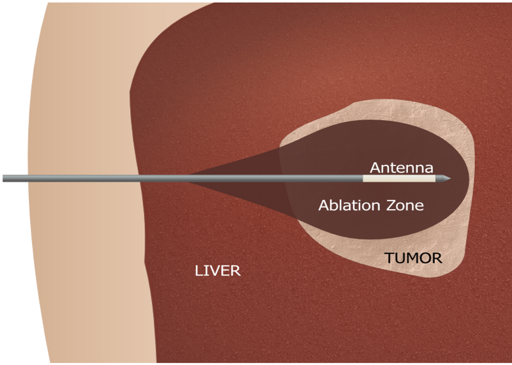
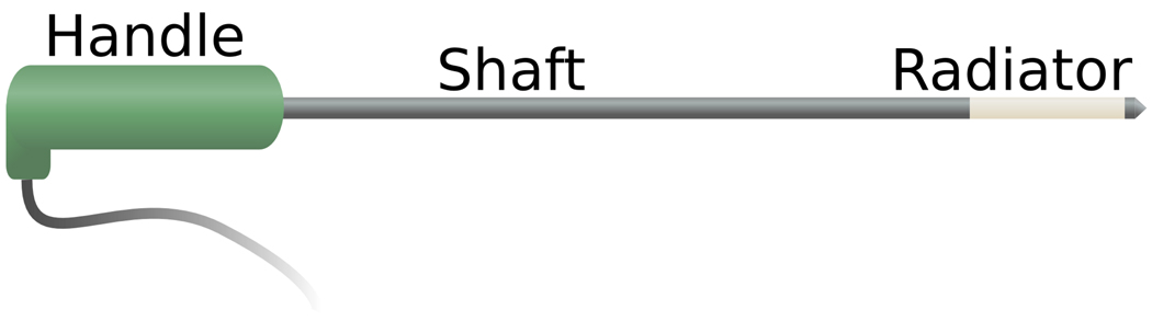
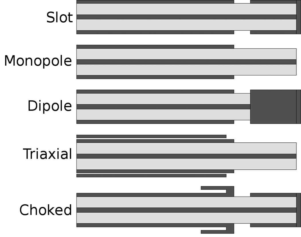
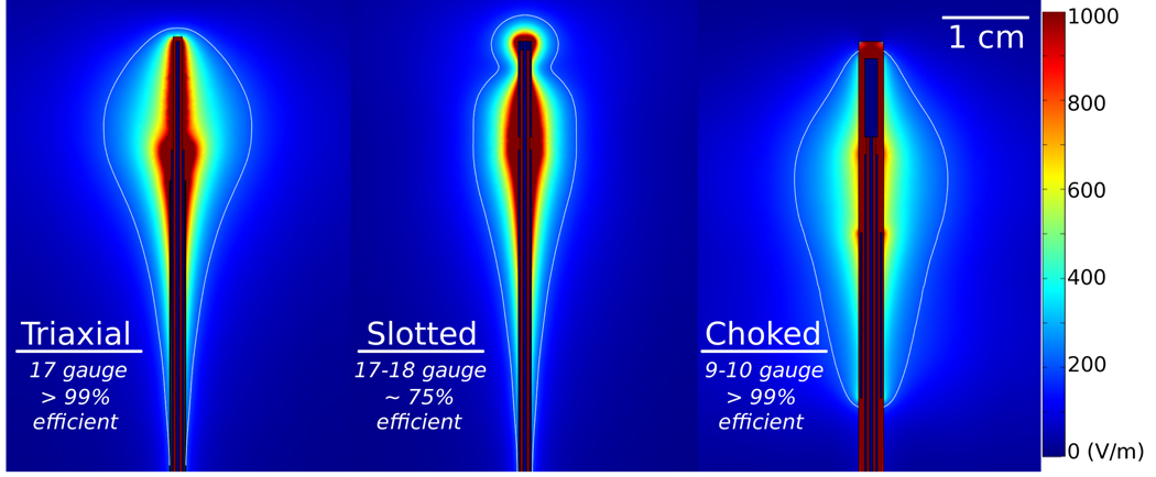
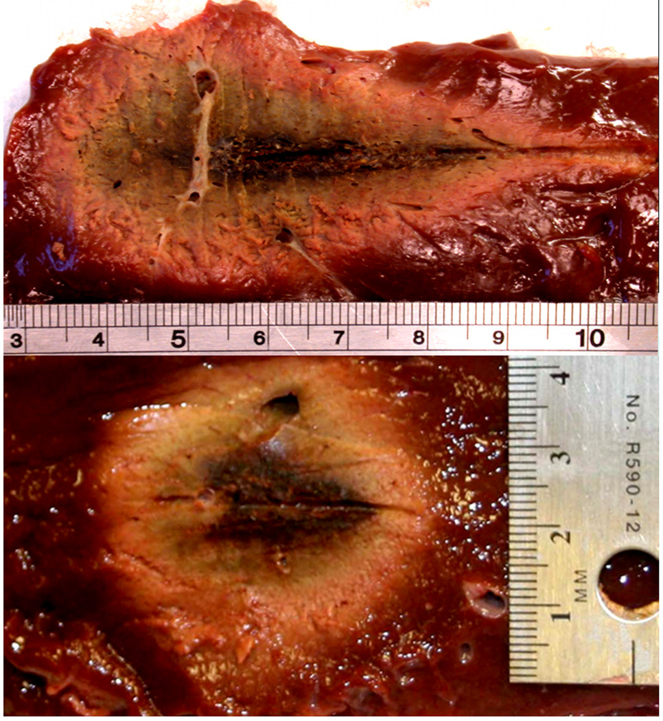
Microwave ablation is an emerging treatment option for many cancers, cardiac arrhythmias, and other medical conditions. During treatment, microwaves are applied directly to tissues to produce rapid temperature elevations sufficient to produce immediate coagulative necrosis. The engineering design criteria for each application differ, with individual consideration for factors such as desired ablation zone size, treatment duration, and procedural invasiveness. Recent technological developments in applicator cooling, power control, and system optimization for specific applications promise to increase the utilization of microwave ablation in the future. This article reviews the basic biophysics of microwave tissue heating, provides an overview of the design and operation of current equipment, and outlines areas for future research.


Figures

Figure 1
Figure 1
Microwave ablation of a liver tumor. The antenna is placed percutaneously into the tumor mass before microwave energy is applied to heat the tumor to cytotoxic levels.
Figure 2
Figure 2
Temperatures measured 5 mm from a microwave (MW) and RF applicator during ablation of the renal cortex. Temperatures can exceed 100 °C during microwave ablation due to electromagnetic propagation through dehydrated, charred or desiccated tissue. Power was pulsed during RF ablation to prevent charring, limiting the maximum temperature to less than 100 °C. Heating rates during microwave ablation can also be more rapid than during RF ablation at the same power levels.
Figure 3
Figure 3
Thermal ablations created in the liver (a-b), kidney (c-d) and lung (e-f). In the liver, both single (a) and three-antenna (b) microwave ablation were used, each delivering approximately 65 W for 10 min. In the kidney and lung, both RF (c,e) and microwave (d,f) are compared. In each tissue microwaves produced larger zones of ablation, especially with multiple antennas.–
Figure 4
Figure 4
Power handling ability (solid lines) and loss (dashed line, dB/m) of two semi-rigid coaxial cables: UT-47 (black, squares) and UT-85 (red, diamonds). Power loss increases with frequency and decreases with cable diameter, creating a trade-off between antenna invasiveness and power handling ability (www.micro-coax.com).
Figure 5
Figure 5
Cartoon schematic of a typical microwave ablation antenna. Coaxial cable runs the length of the shaft, with the radiating element at the distal end of the antenna. Energy is produced around the radiating element.
Figure 6
Figure 6
Schematic cross sections of five antenna designs for microwave ablation. From top to bottom: slot, monopole, dipole, triaxial and choked slot. Metallic components are represented in dark gray, dielectric insulators in light gray.
Figure 7
Figure 7
Electric fields produced by three different antenna designs, representing designs using a linear element (triaxial, left), a single coaxial slot (center) and choked dipole (right). Approximate antenna diameter and power efficiency (1 – reflection coefficient) are noted to illustrate the design balance in each design.
Figure 8
Figure 8
Comparison of ablations created by using a triaxial antenna without cooling (above) and with cryogenic gas cooling (below). The uncooled antenna produces a tear-drop shaped ablation with thermal damage to the tissue surrounding the antenna shaft, but the cooled antenna produces a more spherical ablation without shaft heating.
Figure 9
Figure 9
Ablations created using a total power of 90 W applied by a single antenna with 2.2 mm diameter (left), two antennas with 1.5 mm diameter each (45 W per antenna, center), or three antennas with 1.2 mm diameter (30 W per antenna, right). Simultaneous application of multiple antennas produces ablations with greater size and equivalent shape to a single antenna due to improved spatial distribution of energy.
Figure 10
Figure 10
Cross-section of electric fields produced by four antennas with phase control: a) all antennas at equal phase, b) left and right antennas 180° apart, c) top and bottom antennas 180° apart, and d) diagonal antennas 180° apart. Zones of constructive and destructive interference can be created with phase control of each channel.

References

    1. Bakker JF, Paulides MM, Westra AH, Schippers H, Van Rhoon GC. Design and test of a 434 MHz multi-channel amplifier system for targeted hyperthermia applicators. Int J Hyperthermia. 2010;26:158–170. - PubMed
    1. Converse M, Bond EJ, Van Veen BD, Hagness SC. A computational study of ultra-wideband versus narrowband microwave hyperthermia for breast cancer treatment. IEEE Trans Microw Theory Tech. 2006;54:2169–2180.
    1. Balanis CA. Advanced engineering electromagnetics. New York: John Wiley & Sons; 1989.
    1. Pennes HH. Temperature of skeletal muscle in cerebral hemiplegia and paralysis agitans. Arch Neurol Psychiatry. 1949;62:269–279. - PubMed
    1. Gabriel S, Lau RW, Gabriel C. The dielectric properties of biological tissues: ii. measurements in the frequency range 10 hz to 20 GHz. Phys Med Biol. 1996;41:2251–2269. - PubMed