. 2011 Mar;187(3):731-48.
doi: 10.1534/genetics.110.123752. Epub 2010 Dec 31.

Mechanism of chromosomal boundary action: roadblock, sink, or loop?

Affiliations

Mechanism of chromosomal boundary action: roadblock, sink, or loop?

Daryl Gohl et al. Genetics. 2011 Mar.

Abstract

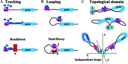
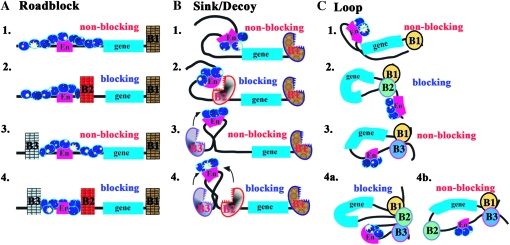
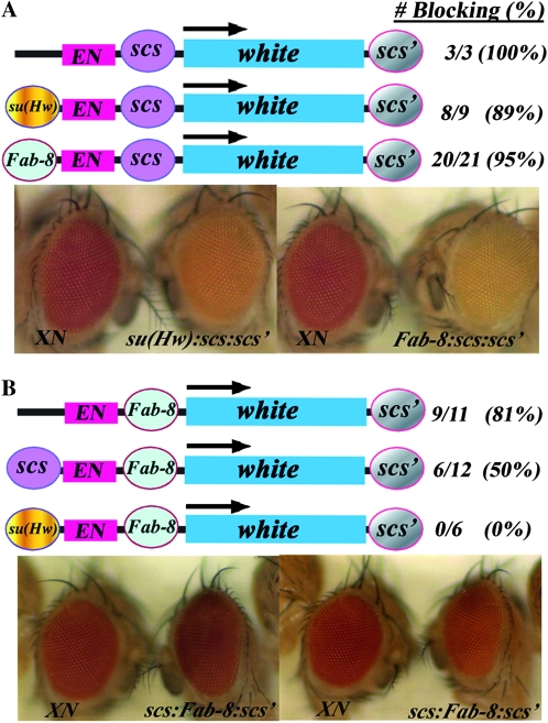
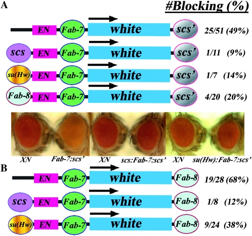
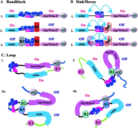
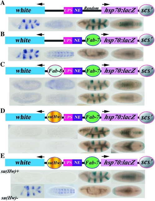
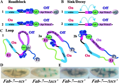
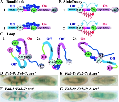
Boundary elements or insulators subdivide eukaryotic chromosomes into a series of structurally and functionally autonomous domains. They ensure that the action of enhancers and silencers is restricted to the domain in which these regulatory elements reside. Three models, the roadblock, sink/decoy, and topological loop, have been proposed to explain the insulating activity of boundary elements. Strong predictions about how boundaries will function in different experimental contexts can be drawn from these models. In the studies reported here, we have designed assays that test these predictions. The results of our assays are inconsistent with the expectations of the roadblock and sink models. Instead, they support the topological loop model.


Figures

F<sc>igure</sc> 1.—
Figure 1.—
Enhancer blocking in the roadblock, sink, and loop domain models. (Top to bottom) (A) In the tracking model, regulatory factors (blue ovals) first assemble at the enhancer (or silencer) (En) and then move processively along the chromatin fiber toward the promoter of the regulatory target. In this model, boundaries (B in section A) act as roadblocks or barriers, preventing the processive movement of the regulatory factors. (B) In the looping model, regulatory factors associate with the enhancer (or silencer) (En). These bound factors then contact the promoter of the regulatory target by the looping over of the chromatin fiber. In this model, boundaries (B in section B) act as sinks, capturing (or repelling) the looping enhancer/DNA complex before it can make contact with the target promoter. Unlike the roadblock model where boundary action is passive, boundaries (B) must actively block regulatory interactions in the looping model. (C) In the topological loop domain model, the chromosome is subdivided by boundaries into a series of topologically independent loops. Enhancers/silencers (En) would contact their regulatory targets by the sliding of the chromatin fiber in the loop against itself (which formally is a combination of both tracking and looping). In this illustration, the enhancer is located 3′ to the transcription unit rather than 5′ as in A and B. Genes are topologically isolated from regulatory elements in adjacent loops, and contacts can only be made by a search in three-dimensional space. In this and subsequent figures, the proximal and distal endpoints of each looped domain are delimited through interactions between boundaries. The endpoints of the looped domain could also be defined by boundary interactions with the nuclear matrix, the chromosome scaffold, or insulator bodies.
F<sc>igure</sc> 2.—
Figure 2.—
Triple boundary assay. The starting transgene used for the triple boundary assay has a white reporter (“gene” indicated by blue line) and the white enhancer (En, red line). As shown in A–C1, a boundary (B1), either scs′ or Fab-8, is placed downstream of the reporter. Additional boundaries are then introduced into the transgene in between the enhancer and the reporter and upstream of the enhancer as indicated in 2, 3, and 4. As shown in A–C1, the white enhancer is expected to activate white (nonblocking) in all three models when the transgene contains only a single boundary downstream of the reporter. Likewise in A–C2, a boundary placed between the white enhancer and reporter (B2) will block activation (blocking) in all three models. As shown in 3, no blocking (nonblocking) will be observed when a boundary is placed upstream (B3) of the white enhancer in the roadblock (A3) and loop (C3) models. In the sink (B3) model, the upstream boundary should have the potential to capture (arrow) the looping enhancer before it can contact the promoter and thus some attenuation of enhancer activity could be observed. In 4, boundaries are placed upstream of the enhancer (B3) and in between the enhancer and the reporter (B2). In the roadblock model (A4), the addition of an upstream boundary (B3) should have no effect on the blocking activity (blocking) of the interposed (B2) boundary. In the sink/decoy model (B4), flanking the enhancer with boundaries is predicted to have no effect or increase blocking activity (see arrows in 4). In the loop model, blocking activity can be maintained or lost depending on how the loops are defined. As illustrated in C4a, blocking activity will be maintained if the enhancer and gene are in separate loops (via boundary interactions as illustrated, or by interactions with the nuclear matrix/chromosome scaffold). In C4b, blocking will be lost (nonblocking) if the loop is defined by the upstream (B3) and downstream boundaries (B1) (Note that the 3′ end of the white reporter also contains the recently described wari insulator (Chetverina et al. 2008), though it is not indicated here. The presence of wari does not alter the predictions of each model. Moreover, this boundary does not appear to insulate in combination with scs or Fab-7).
F<sc>igure</sc> 3.—
Figure 3.—
Triple boundary with scs or Fab-8 in the middle. (A) scs in between the white enhancer and the white reporter. When scs is interposed between the enhancer and reporter, blocking is observed in all of the lines (3 X-scs-scs′ lines were reported in Vazquez and Schedl (1994). scs is then challenged by placing su(Hw) or Fab-8 upstream of the enhancer. In each case, blocking is retained in the majority of the transgenic lines. The photographs show eyes of flies transformed with the starting transgene XN (Hagstrom et al. 1996), which has scs′ downstream of the white reporter but no other boundaries and flies transformed with either the su(Hw):scs:scs′ transgene or the Fab-8:scs:scs′ transgene as indicated. Flies transgenic for the starting transgene, XN, have red eyes, while flies transgenic for either su(Hw):scs:scs′ (8/9) or Fab-8:scs:scs′ (20/21) have yellow to orange eyes as illustrated. (B) Fab-8 in between the white enhancer and the white reporter. When Fab-8 is interposed between the enhancer and the reporter, blocking is observed in ∼80% of the lines and the eye color ranges from light yellow to orange (like that illustrated for su(Hw)scs:scs′ and Fab-8:scs:scs′ in A). Half of the lines retain blocking when Fab-8 is challenged by an upstream scs (6/12) and have yellow to orange eye color. None of the lines (0/6) show blocking when Fab-8 is challenged with su(Hw). Photographs in B show examples of two of the nonblocking lines for scs:Fab-8:scs′.
F<sc>igure</sc> 4.—
Figure 4.—
Triple boundary with Fab-7 in the middle. (A) Fab-7 in between the white enhancer and the white reporter and scs′ downstream. When Fab-7 is interposed between the enhancer and reporter, blocking is observed in 50% of the transgenic lines (Hagstrom et al. 1996); compare XN to Fab-7:scs′ on the left. Fab-7 is then challenged by placing scs (see scs:Fab-7:scs′ in the middle), su(Hw) (see su(Hw):Fab-7:scs′ on the right) or Fab-8 (not shown) upstream of the enhancer. In all three cases, Fab-7 blocking is compromised, and the number of transgenic lines showing blocking activity is reduced. (B) Fab-7 in between the white enhancer and the white reporter with Fab-8 rather scs′ downstream of the reporter. Replacing the downstream scs′ with Fab-8 improves Fab-7 blocking activity and instead of 50%, ∼70% of the transgenic lines have blocking activity. When scs is placed upstream of the white enhancer, Fab-7 blocking activity is again absent in most of the transgenic lines. While Fab-7 blocking activity in this transgene is also reduced when su(Hw) is placed upstream of the white enhancer, the effects of su(Hw) are not as strong as those observed in the transgene that has scs′ downstream of the reporter.
F<sc>igure</sc> 5.—
Figure 5.—
Domain definition assay. The transgene in the domain definition assay has white (blue) and hsp70:lacZ (mauve) reporters flanking two enhancers, the UPS stripe enhancer (red) and the NE neurogenic (purple) enhancer, from the ftz gene, which are active during early and midembryogenesis. scs′ is located downstream of the hsp70:lacZ reporter. Additional boundaries are then introduced into the transgene between the ftz enhancers and the hsp70:lacZ reporter (B2) and/or between the ftz enhancers and the white reporter (B3). As shown in A–C1, the ftz enhancers are expected to activate both the white and hsp70:lacZ reporters in all three models when there are no intervening boundaries (On). In (A–C2), a boundary (B2) placed between the ftz enhancers and the hsp70:lacZ reporter is expected to generate two regulatory domains, one containing the hsp70:lacZ reporter and the other containing the ftz enhancers and the white reporter. In this domain configuration, the ftz enhancers will activate the lacZ (Off) but not the white (On) reporter in all three models. Similarly, a boundary (B3) placed between the ftz enhancers and white is expected to block activation of the white but not the hsp70:lacZ reporter in all three models (not shown). As indicated in 3 for the roadblock (A) and sink (B) models, flanking the ftz enhancers with boundaries B2 and B3 will subdivide the transgene into three independent domains, containing, respectively, white, the ftz enhancers, and hsp70:lacZ. In the loop model, domain definition depends on the identity and relative position of the boundary elements in the transgene and in the neighboring chromosomal DNA segments. Among the many possible domain configurations, two different examples are shown for the loop model in C3a and C3b. In C3a, a loop domain is defined by B2 and B3 [interacting with each other as shown, or with some nuclear structure(s)]. This subdivides the transgene into three separate regulatory domains are formed containing, respectively, white, the ftz enhancers and hsp70:lacZ. In this case both reporters are protected from the ftz enhancers. In C3b, a loop domain is defined by B3 and scs′. This subdivides the transgene into a domain containing white, and a domain containing the ftz enhancers, boundary B2 and the hsp70:lacZ reporter. In this case, the ftz enhancers are blocked from activating white, but are not prevented from activating hsp70:lacZ.
F<sc>igure</sc> 6.—
Figure 6.—
Domain definition depends upon boundary identity and relative position. (A) In the starting transgene containing a random segment of Drosophila DNA (from the Bicaudal-D locus) or no DNA (not shown) in between the ftz enhancers and the hsp70:lacZ reporter the ftz enhancers activate both white and hsp70:lacZ. Lines are from Hagstrom et al. (1996). Note that the NE enhancer does not activate white when a competing hsp70:lacZ reporter is accessible. (B) When Fab-7 is placed between the ftz enhancers and the hsp70:lacZ reporter, it subdivides the transgene into two independent regulatory domains. Lines are from Hagstrom et al. (1996). One domain contains white and the ftz enhancers, while the other domain contains the hsp70:lacZ reporter. In this configuration of regulatory domains, the ftz enhancers drive white expression but are blocked from activating hsp70:lacZ expression. (C) The regulatory domains in B are redefined when Fab-8 is interposed between the ftz enhancers and white. In the first example, both ftz enhancers now drive hsp70:lacZ expression, while they no longer activate white. From this pattern of gene activity, we infer that the organization of regulatory domains resembles that in Figure 5, 3b. The ftz enhancers (along with Fab-7) are now in the same regulatory domain as hsp70:lacZ, while white is in a separate regulatory domain. In the second example, the ftz UPS enhancer activates hsp70:lacZ, but not white, while the NE enhancer activates neither of the reporters. From this pattern of gene activity we infer that the organization of regulatory domains at the time when the UPS enhancer is active resembles that in Figure 5, 3b. Later in development, when the NE enhancer is active, the organization of regulatory domains changes and it resembles that shown in Figure 5, 3a. In this case, the ftz NE enhancer is separated from both white and hsp70:lacZ and neither reporter is activated. (D) A similar pattern of domain redefinition is observed when su(Hw) is interposed between the ftz enhancers and white. In 9 of 10 transgenic lines, the ftz UPS enhancer activates hsp70:lacZ, but not white (D, upper and lower panels, Figure 5, 3b), while in the remaining line neither reporter is active (Figure 5, 3a). In midembryogenesis, the Fab-7 boundary is inactive in half of the lines, and the ftz NE enhancer activates hsp70:lacZ but not white (D, top panel). In the remaining lines, Fab-7 boundary activity is reestablished and neither reporter is active (D, bottom panel). (E) Domain redefinition depends upon a functional su(Hw) boundary. In this example, both ftz enhancers drive hsp70:lacZ expression but not white in wild-type flies, while in su(Hw) mutant flies where the su(Hw) boundary is inactive, the ftz enhancers activate white, but not hsp70:lacZ.
F<sc>igure</sc> 7.—
Figure 7.—
Single or in combination? Predictions of the barrier, sink/decoy, and loop models when the downstream scs′ boundary is present or absent are shown in A–C. When scs′ is present (A–C, 1) all three models predict that the Fab-7 boundary will block the ftz enhancer from activating hsp70:lacZ. In the barrier and sink/decoy models blocking activity is an intrinsic property of a boundary. Consequently, as shown in A2 and B2, removing the downstream scs′ boundary should have no effect on Fab-7, and it should still block the ftz enhancers from activating hsp70:lacZ. In contrast, in the loop model, the regulatory domains will be redefined whenever a boundary is removed or added. In the redefined domains, Fab-7 could still block the ftz enhancers from activating hsp70:lacZ (C2a), or Fab-7 blocking activity could be lost (C2b). In the former case, a looped domain would be defined by Fab-7 and an endogenous boundary upstream of the transgene insertion site (E1). In the later case, a looped domain is formed between boundaries upstream (E1) and downstream (E2) of the transgene insertion site. (D and E) UPS-dependent stripe expression (Fab-7–scs′) before and after (Fab-7–Δscs′) for two different transgenic lines. In both lines, Fab-7 blocks the UPS enhancer in the Fab-7–scs′ transgene, and there is only a low level of hsp70:lacZ stripe expression as seen previously for Fab-7 (Hagstrom et al. 1996). However, when scs′ is deleted, UPS-dependent stripe expression is activated.
F<sc>igure</sc> 8.—
Figure 8.—
Boundary resurrection. In the roadblock and sink/decoy novel mechanisms must be postulated to account for the loss of Fab-7 blocking activity in the domain definition assay. One mechanism, illustrated for the roadblock model in A1, postulates that when enhancers are tightly confined by two flanking boundaries, excess enhancer activity accumulates and eventually overcomes the weaker boundary. A second mechanism, illustrated for the sink/decoy model in B1, postulates that certain boundaries have a novel ability to neutralize or inactivate (red arrows) other nearby boundaries. A2 and B2 show that the special mechanisms postulated to cause the loss of Fab-7 blocking activity in the barrier and sink/decoy models (confining the ftz enhancers or boundary inactivation) should be completely indifferent to the presence or absence of a downstream scs′ element. In contrast, the loop model predicts that the configuration of regulatory domains will be redefined whenever a boundary is removed. In C2a, Fab-7 and Fab-8 define a new domain that contains the ftz enhancers. In this domain configuration, Fab-7 boundary activity will be restored. In C2b, the new domain is formed by Fab-8 and an endogenous boundary (E2) downstream of the transgene insertion site. In this configuration, the ftz enhancers, Fab-7 and hsp70:lacZ, are in the same regulatory domain, and the reporter will be activated. (D–G) UPS- and NE-dependent hsp70:lacZ activity before (D and F) and after (E and G) the removal of scs′ for two different transgenic lines.

References

    1. Alfert, M., 1954. Composition and structure of giant chromosomes. Int. Rev. Cytol. 3 131–176.
    1. Ameres, S. L., L. Drueppel, K. Pfleiderer, A. Schmidt, W. Hillen et al., 2005. Inducible DNA-loop formation blocks transcriptional activation by an SV40 enhancer. EMBO J. 24 358–367. - PMC - PubMed
    1. Aoki, T., S. Schweinsberg, J. Manasson and P. Schedl, 2008. A stage-specific factor confers Fab-7 boundary activity during early embryogenesis in Drosophila. Mol. Cell. Biol. 28 1047–1060. - PMC - PubMed
    1. Barges, S., J. Mihaly, M. Galloni, K. Hagstrom, M. Muller et al., 2000. The Fab-8 boundary defines the distal limit of the bithorax complex iab-7 domain and insulates iab-7 from initiation elements and a PRE in the adjacent iab-8 domain. Development 127 779–790. - PubMed
    1. Bellard, M., M. T. Kuo, G. Dretzen and P. Chambon, 1980. Differential nuclease sensitivity of the ovalbumin and beta-globin chromatin regions in erythrocytes and oviduct cells of laying hen. Nucleic Acids Res. 8 2737–2750. - PMC - PubMed

Publication types

MeSH terms

LinkOut - more resources