

Structure of the Drosophila apoptosome at 6.9 å resolution
- PMID: 21220123
- PMCID: PMC3053581
- DOI: 10.1016/j.str.2010.10.009
Structure of the Drosophila apoptosome at 6.9 å resolution
Abstract
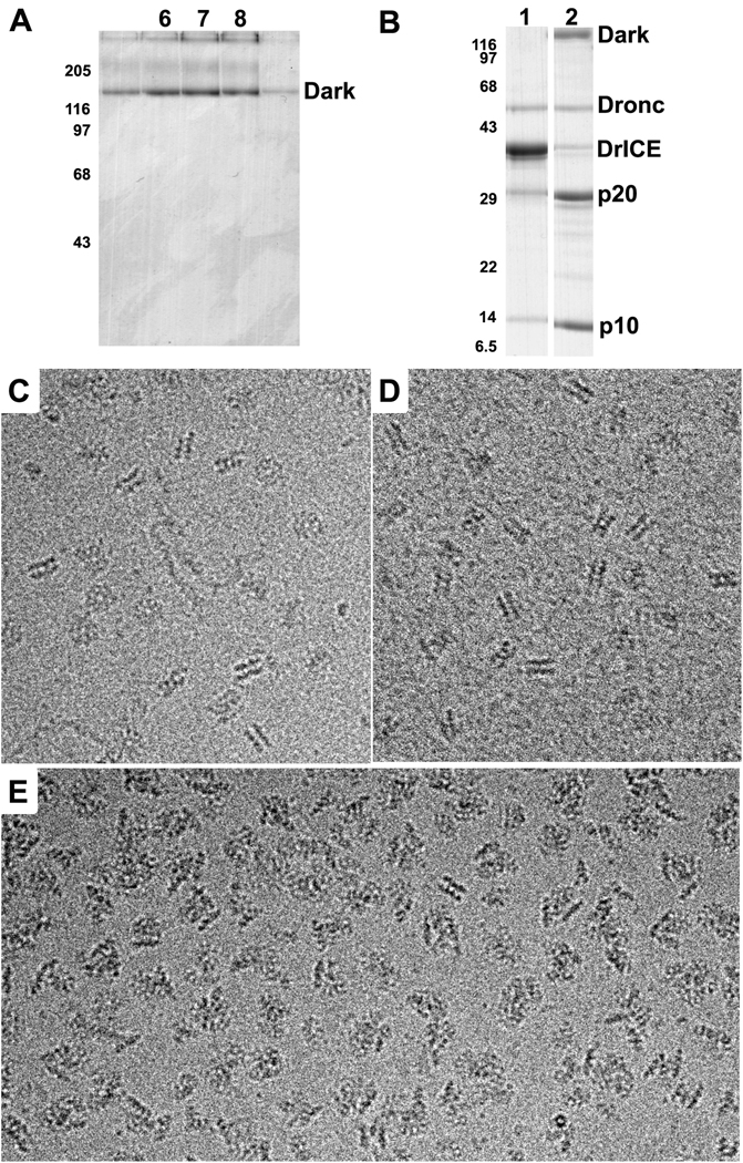
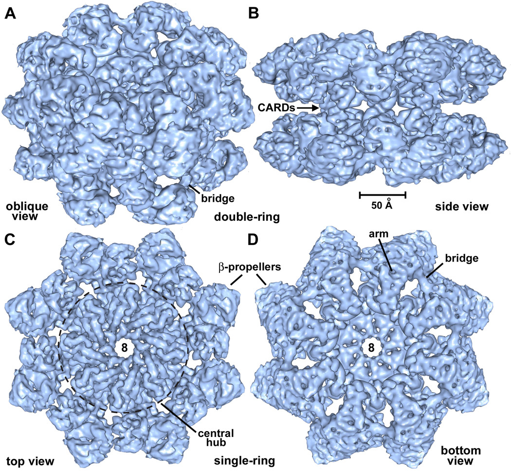
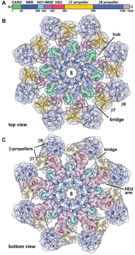
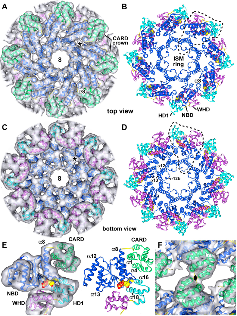
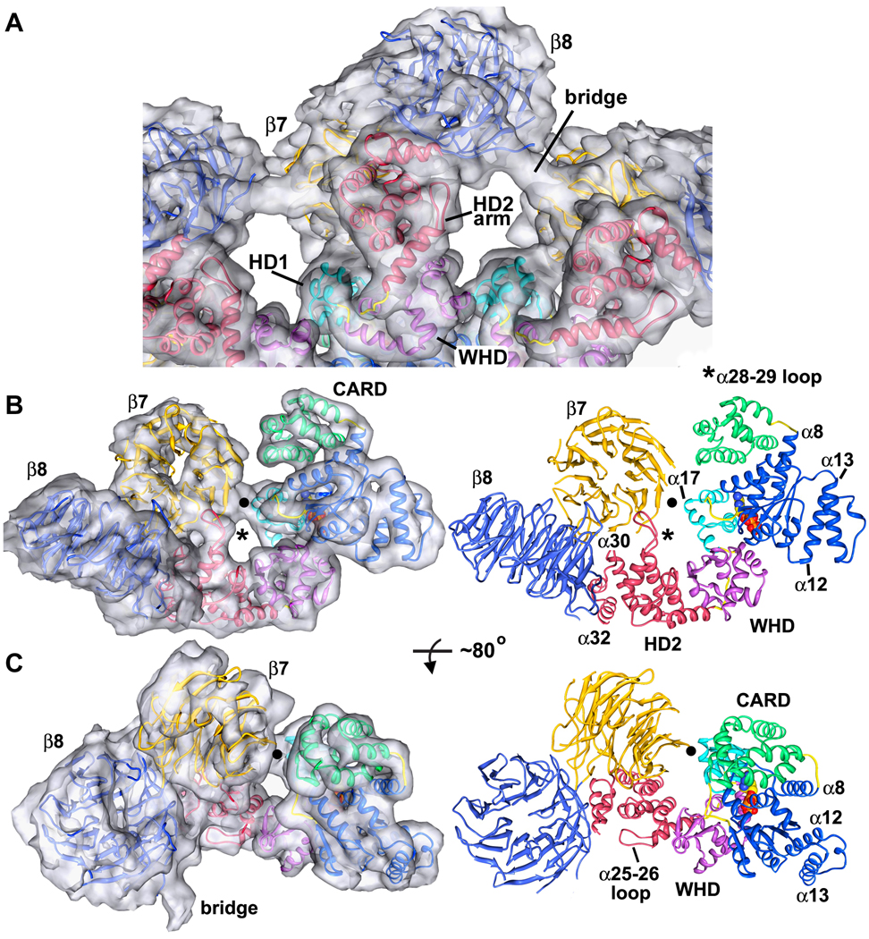
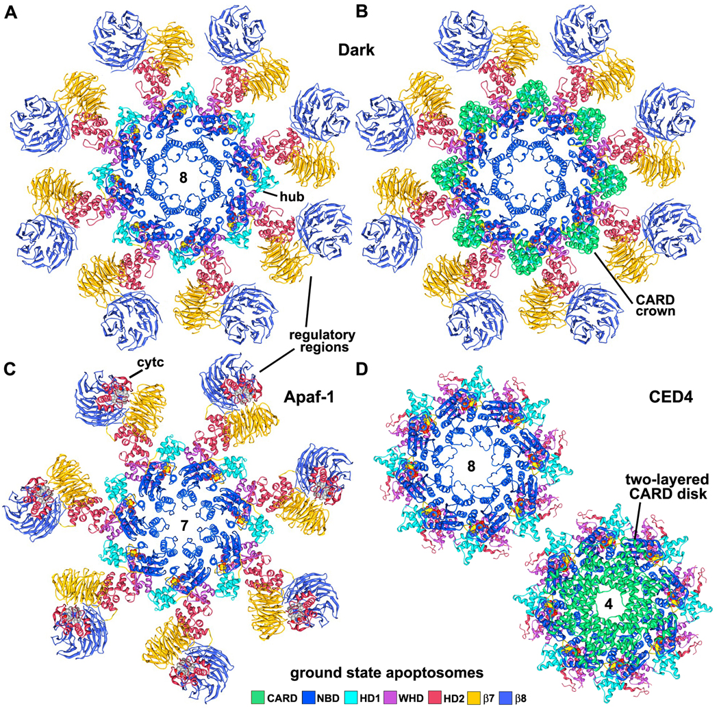
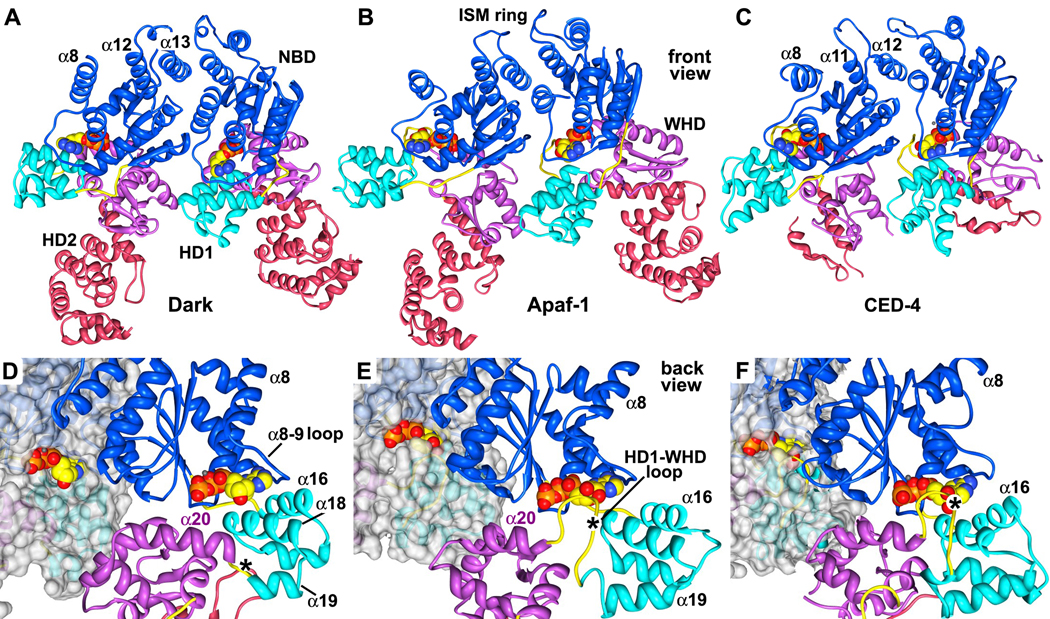
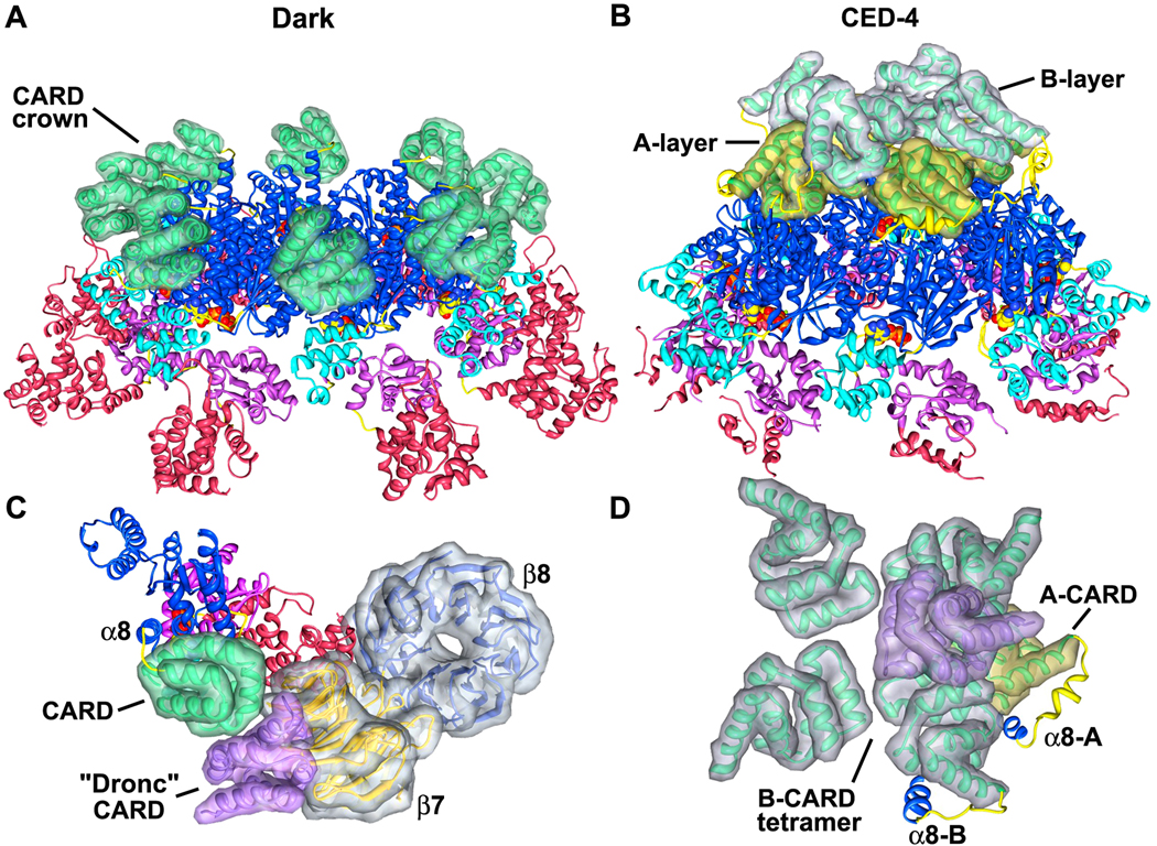
The Drosophila Apaf-1 related killer forms an apoptosome in the intrinsic cell death pathway. In this study we show that Dark forms a single ring when initiator procaspases are bound. This Dark-Dronc complex cleaves DrICE efficiently; hence, a single ring represents the Drosophila apoptosome. We then determined the 3D structure of a double ring at ∼6.9 Å resolution and created a model of the apoptosome. Subunit interactions in the Dark complex are similar to those in Apaf-1 and CED-4 apoptosomes, but there are significant differences. In particular, Dark has "lost" a loop in the nucleotide-binding pocket, which opens a path for possible dATP exchange in the apoptosome. In addition, caspase recruitment domains (CARDs) form a crown on the central hub of the Dark apoptosome. This CARD geometry suggests that conformational changes will be required to form active Dark-Dronc complexes. When taken together, these data provide insights into apoptosome structure, function, and evolution.
Copyright © 2011 Elsevier Ltd. All rights reserved.
Figures
Comment in
-
DARK apoptosome secrets come to light.Structure. 2011 Jan 12;19(1):4-6. doi: 10.1016/j.str.2010.12.009. Structure. 2011. PMID: 21220110 Free PMC article.
Similar articles
-
Structure of the apoptosome: mechanistic insights into activation of an initiator caspase from Drosophila.Genes Dev. 2015 Feb 1;29(3):277-87. doi: 10.1101/gad.255877.114. Genes Dev. 2015. PMID: 25644603 Free PMC article.
-
A Near-Atomic Structure of the Dark Apoptosome Provides Insight into Assembly and Activation.Structure. 2017 Jan 3;25(1):40-52. doi: 10.1016/j.str.2016.11.002. Epub 2016 Dec 1. Structure. 2017. PMID: 27916517 Free PMC article.
-
New insights into apoptosome structure and function.Cell Death Differ. 2018 Jul;25(7):1194-1208. doi: 10.1038/s41418-017-0025-z. Epub 2018 May 15. Cell Death Differ. 2018. PMID: 29765111 Free PMC article. Review.
-
Dark and Dronc activation in Drosophila melanogaster.Proc Natl Acad Sci U S A. 2024 Feb 27;121(9):e2312784121. doi: 10.1073/pnas.2312784121. Epub 2024 Feb 21. Proc Natl Acad Sci U S A. 2024. PMID: 38381783 Free PMC article.
-
Apoptosome: a platform for the activation of initiator caspases.Cell Death Differ. 2007 Jan;14(1):56-65. doi: 10.1038/sj.cdd.4402028. Epub 2006 Sep 15. Cell Death Differ. 2007. PMID: 16977332 Review.
Cited by
-
Understanding Developmental Cell Death Using Drosophila as a Model System.Cells. 2024 Feb 16;13(4):347. doi: 10.3390/cells13040347. Cells. 2024. PMID: 38391960 Free PMC article. Review.
-
Structural insight into negative DNA supercoiling by DNA gyrase, a bacterial type 2A DNA topoisomerase.Nucleic Acids Res. 2013 Sep;41(16):7815-27. doi: 10.1093/nar/gkt560. Epub 2013 Jun 26. Nucleic Acids Res. 2013. PMID: 23804759 Free PMC article.
-
How 'arm-twisting' by the inducer triggers activation of the MalT transcription factor, a typical signal transduction ATPase with numerous domains (STAND).Nucleic Acids Res. 2015 Mar 31;43(6):3089-99. doi: 10.1093/nar/gkv158. Epub 2015 Mar 3. Nucleic Acids Res. 2015. PMID: 25740650 Free PMC article.
-
Formation and structure of a NAIP5-NLRC4 inflammasome induced by direct interactions with conserved N- and C-terminal regions of flagellin.J Biol Chem. 2012 Nov 9;287(46):38460-72. doi: 10.1074/jbc.M112.393512. Epub 2012 Sep 25. J Biol Chem. 2012. PMID: 23012363 Free PMC article.
-
Dmp53, basket and drICE gene knockdown and polyphenol gallic acid increase life span and locomotor activity in a Drosophila Parkinson's disease model.Genet Mol Biol. 2013 Dec;36(4):608-15. doi: 10.1590/S1415-47572013000400020. Epub 2013 Nov 8. Genet Mol Biol. 2013. PMID: 24385865 Free PMC article.
References
-
- Acehan D, Jiang X, Morgan DG, Heuser JE, Wang X, Akey CW. Three-dimensional structure of the apoptosome: implications for assembly, procaspase-9 binding and activation. Mol. Cell. 2002;9:423–432. - PubMed
-
- Boatright KM, Renatus M, Scott FL, Sperandio S, Shin H, Pedersen IM, Ricci JE, Edris WA, Sutherlin DP, Green DR, Salvesen GS. A unified model for apical caspase activation. Mol. Cell. 2003;11:529–541. - PubMed
-
- Chai J, Yan N, Huh JR, Wu JW, Li W, Hay BA, Shi Y. Molecular mechanism of Reaper-Grim-Hid-mediated suppression of DIAP1-dependent Dronc ubiquitination. Nature Struct. Biol. 2003;10:892–898. - PubMed
-
- Chew SK, Akdemir F, Chen P, Lu WJ, Mills K, Daish T, Kumar S, Rodriguez A, Abrams JM. The apical caspase dronc governs programmed and unprogrammed cell death in Drosophila. Dev. Cell. 2004;7:897–907. - PubMed
Publication types
MeSH terms
Substances
Associated data
- Actions
- Actions
- Actions
Grants and funding
LinkOut - more resources
Full Text Sources
Molecular Biology Databases
