. 2011 Feb 1;108(5):1788-93.
doi: 10.1073/pnas.1015440108. Epub 2011 Jan 18.

Dynamically tunable hemispherical electronic eye camera system with adjustable zoom capability

Affiliations

Dynamically tunable hemispherical electronic eye camera system with adjustable zoom capability

Inhwa Jung et al. Proc Natl Acad Sci U S A. .

Abstract

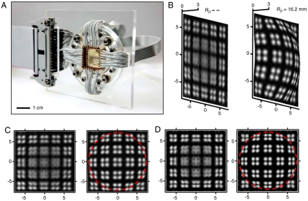
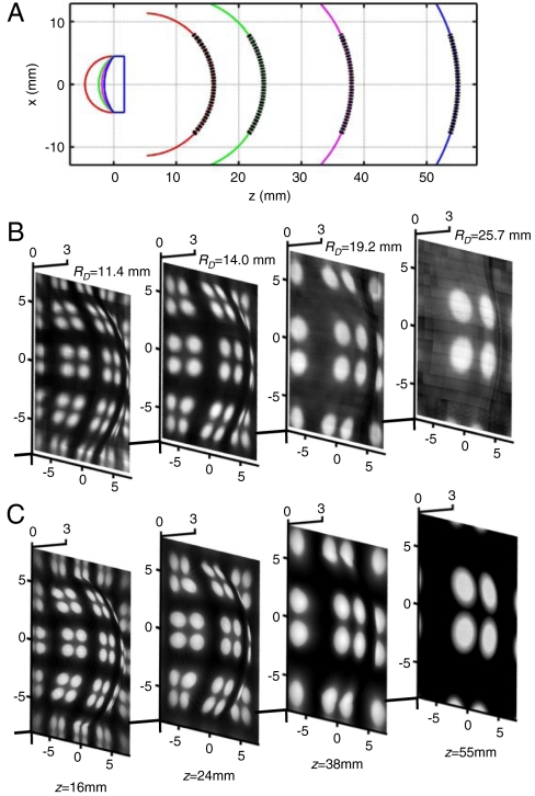
Imaging systems that exploit arrays of photodetectors in curvilinear layouts are attractive due to their ability to match the strongly nonplanar image surfaces (i.e., Petzval surfaces) that form with simple lenses, thereby creating new design options. Recent work has yielded significant progress in the realization of such "eyeball" cameras, including examples of fully functional silicon devices capable of collecting realistic images. Although these systems provide advantages compared to those with conventional, planar designs, their fixed detector curvature renders them incompatible with changes in the Petzval surface that accompany variable zoom achieved with simple lenses. This paper describes a class of digital imaging device that overcomes this limitation, through the use of photodetector arrays on thin elastomeric membranes, capable of reversible deformation into hemispherical shapes with radii of curvature that can be adjusted dynamically, via hydraulics. Combining this type of detector with a similarly tunable, fluidic plano-convex lens yields a hemispherical camera with variable zoom and excellent imaging characteristics. Systematic experimental and theoretical studies of the mechanics and optics reveal all underlying principles of operation. This type of technology could be useful for night-vision surveillance, endoscopic imaging, and other areas that require compact cameras with simple zoom optics and wide-angle fields of view.


Conflict of interest statement

The authors declare no conflict of interest.

Figures

Fig. 1.
Fig. 1.
(A) Schematic illustration of the camera, including the tunable lens (Upper) and tunable detector (Lower) modules. The lens consists of a fluid-filled gap between a thin (0.2 mm) PDMS membrane and a glass window (1.5-mm thick), to form a plano-convex lens with 9-mm diameter and radius of curvature that is adjustable with fluid pressure. The tunable detector consists of an array of interconnected silicon photodiodes and blocking diodes (16 × 16 pixels) mounted in a thin (0.4 mm) PDMS membrane, in a mechanically optimized, open mesh serpentine design. This detector sheet mounts on a fluid-filled cavity; controlling the pressure deforms the sheet into concave or convex hemispherical shapes with well-defined, tunable levels of curvature. (B) Photograph of a complete camera. (C) Photographs of the photodetector array imaged through the lens, tuned to different magnifications. The left and right images were acquired at radius of curvature in the lens of 5.2 and 7.3 mm. In both cases, the radius of curvature of the detector surface was 11.4 mm. The distance of the center part of the detector from the bottom part of the lens was 25.0 mm. (D) Angled view optical images of the tunable lens at three different configurations (Upper), achieved by increasing the fluid pressure from left to right. The lower frame shows measurements of the height and radius of curvature of the lens surface as a function of applied fluid pressure. The results reveal changes that are repeatable and systematic (experimental; □ and ▪ symbols) and quantitatively consistent with analytical calculations of the mechanics (analytical; blue lines) and finite element analysis (FEA, green symbols).
Fig. 2.
Fig. 2.
(A) Tilted view of a photodetector array on a thin membrane of PDMS in flat (Upper) and hemispherically curved (Lower) configurations, actuated by pressure applied to a fluid-filled chamber underneath. (B) Three-dimensional rendering of the profile of the deformed surface measured by a laser scanner. Here, the shape is close to that of a hemisphere with a radius of curvature (RD) of 13.3 mm and a maximum deflection (HD) of 2.7 mm. Calculated (blue) and measured (red) unit cell positions appear as squares on this rendered surface. (Upper) Three-dimensional rendering of circumferential strains in the silicon devices (squares) and the PDMS membrane determined by finite element analysis (Lower). (C) Angled view optical images of the tunable detector in three different configurations (Top), achieved by decreasing the level of negative pressure applied to the underlying fluid chamber from left to right. Measurements of the apex height and radius of curvature of the detector surface as a function of applied fluid pressure reveal changes that are repeatable and systematic (experimental) and quantitatively consistent with analytical calculations of the mechanics (analytical; blue lines) and finite element analysis (FEA, green symbols), as shown in the middle frame. Laser scanning measurements of the profiles of the deformed detector surface show shapes are almost perfectly hemispherical, consistent with analytical mechanics models. Here, each measured profile (symbols) is accompanied by a corresponding analytical calculated result (lines) (Bottom). (D) Optical micrograph of a 2 × 2 array of unit cells, collected from a region near the center of a detector array, in a deformed state (Left) and maximum principal strains in the silicon and metal determined by finite element analysis (Right) for the case of overall biaxial strain of 12%. These strains are far below those expected to cause fracture in the materials.
Fig. 3.
Fig. 3.
(A) Photograph of a deformable detector array with external electrical interconnections. Electrode pins on a mounting plate press against matching electrodes at the periphery of the array to establish connections to a ribbon cable that leads to a data acquisition system. (B) Images of a test pattern of bright circular discs, acquired by the device in flat (Left) and deformed hemispherical (Right) configurations, collected using a glass plano-convex lens (diameter, 9 mm; focal length, 22.8 mm). The images are rendered on surfaces that match those of the detector array. The distance between the lens and the source image is 75 mm. The radius of curvature and the maximum deflection in this deformed state are 16.2 and 2.2 mm, respectively. The image in the flat case was collected at a distance of 5.5 mm closer to the lens than the focal location expected by the thin lens approximation (31.7 mm). In this position, only the far peripheral regions of the image are in focus. The image in the curved configuration was acquired simply by actuating the detector into this shape, without changing any other aspect of the setup. This deformation brings the entire field of view into focus, due to matching of the detector shape to the Petzval surface. (C) Planar projections of these images. The dashed circle indicates the area under deformation. (D) Modeling results corresponding to these two cases, obtained by ray-tracing calculation. The outcomes show quantitative agreement with the measurements. The dashed circle indicates the area under deformation.
Fig. 4.
Fig. 4.
(A) Ray-tracing analysis of the positions and curvatures of the image surfaces (i.e., Petzval surfaces; Right) that form with four different geometries of a tunable plano-convex lens (Left). Actual sizes of detector surfaces are shown as dashed lines. (B) Images acquired by a complete camera system, at these four conditions. These images were collected at distances from the lens (z) of 16, 24, 38, and 55 mm with corresponding radii of curvature of the lens surface (RL) of 4.9, 6.1, 7.3, and 11.5 mm. The radii of curvature (RD) of the detector surface, set to match the computed Petzval surface shape, were 11.4, 14.0, 19.2, and 25.7 mm. These images were acquired by a scanning procedure described in Materials and Methods The object consists of a pattern of light circular discs (diameter, 3.5 mm; pitches between circles, 5 and 8.5 mm). (C) Images computed by ray-tracing analysis, at conditions corresponding to the measured results. The axis scales are in millimeters.

References

    1. Ko HC, et al. A hemispherical electronic eye camera based on compressible silicon optoelectronics. Nature. 2008;454:748–753. - PubMed
    1. Grayson T. Curved focal plane wide field of view telescope design. Proc SPIE. 2002;4849:269–274.
    1. Rim SB, et al. The optical advantages of curved focal plane arrays. Opt Express. 2008;16:4965–4971. - PubMed
    1. Dinyari R, et al. Curving monolithic silicon for nonplanar focal plane array applications. Appl Phys Lett. 2008;92:091114-1–091114-3.
    1. Hung PJ, Jeong KH, Liu GL, Lee LP. Microfabricated suspensions for electrical connections on the tunable elastomer membrane. Appl Phys Lett. 2004;85:6051–6053.

LinkOut - more resources