

doi: 10.1039/B923717H.
Biomedical applications of thermally activated shape memory polymers
Affiliations
- PMID: 21258605
- PMCID: PMC3023912
- DOI: 10.1039/B923717H
Item in Clipboard
Biomedical applications of thermally activated shape memory polymers
J Mater Chem.
.
Abstract
Shape memory polymers (SMPs) are smart materials that can remember a primary shape and can return to this primary shape from a deformed secondary shape when given an appropriate stimulus. This property allows them to be delivered in a compact form via minimally invasive surgeries in humans, and deployed to achieve complex final shapes. Here we review the various biomedical applications of SMPs and the challenges they face with respect to actuation and biocompatibility. While shape memory behavior has been demonstrated with heat, light and chemical environment, here we focus our discussion on thermally stimulated SMPs.
Figures
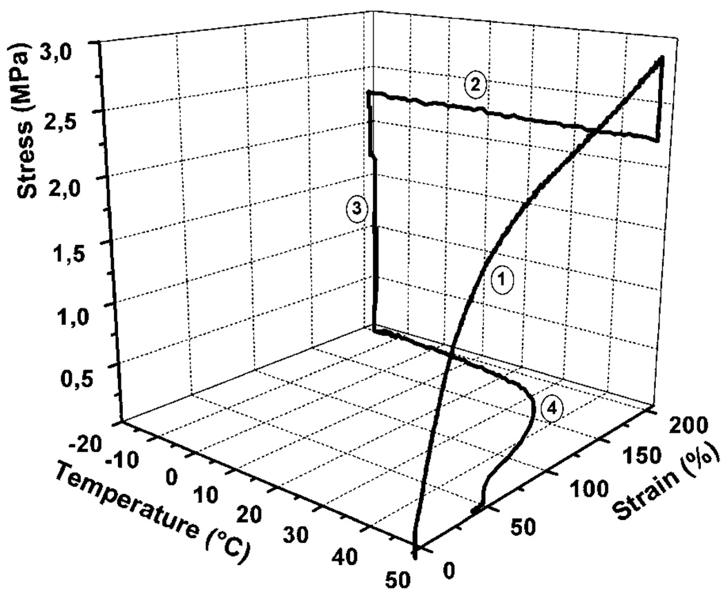
Cyclic thermomechanical experiment of polyurethane synthesized from the reaction of 35 wt% oligo(p-dioxanone) diol and 65 wt% oligo(ε-caprolactone) diol with 2,2(4),4-trimethylhexanediisocyanate. It shows a Ttrans of 40 °C. Results of the first cycle are shown. Step 1 of the experiment is strain-controlled; steps 2 through 4 to beginning of next cycle are stress-controlled. (Reprinted with permission from A. Lendlein and R. Langer, Biodegradable, elastic shape-memory polymers for potential biomedical applications, Science, 2002, 296, 1673.12)
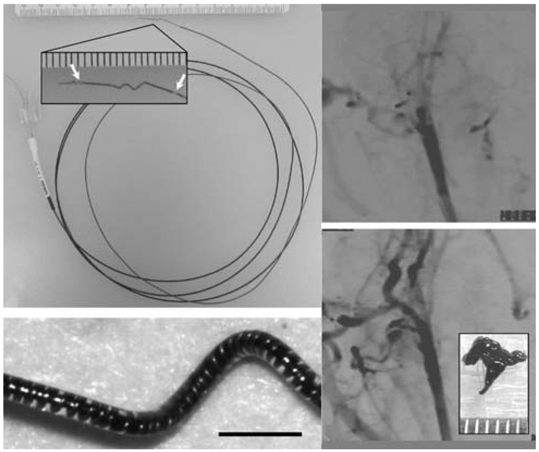
(Top left) Electromechanical embolectomy device in its corkscrew form. The SMP-nitinol corkscrew microactuator is mounted at the distal end of a microcatheter. Ac lose-up of the microactuator showing the radio-opaque gold markers (arrows) is seen in the inset (scale divisions in millimetres). (Bottom left) Microscope image of the microactuator showing the copper-wound nitinol wire encapsulated by the SMP. Scale bar = 1 mm. (Top right) Angiogram showing occlusion of the rabbit common carotid artery. (Bottom right) Post-treatment angiogram showing complete restoration of blood flow. A photograph of the retrieved clot is shown in the inset (scale divisions in millimetres). (Reprinted with permission from J. Hartman, W. Small, IV, T. S. Wilson, J. Brock, P. R. Buckley, W. J. Benett, J. M. Loge and D. J. Maitland, Embolectomy in a rabbit acute arterial occlusion model using a novel electromechanical extraction device, Am. J. Neuroradiol., 2007, 28, 872.63)
(Left) Fluoroscopic image of 3% tantalum-filled SMP coils with varying diameter immersed under 50 cm3 of water. The three coils had coil diameters of 10 mm, and wire diameters of 0.25 (uppermost), 0.45 (lower left), and 0.088 mm (lower right). (Right) Deployment of two SMP coils under simulated flow conditions. (Reprinted with permission from J. M. Hampikian, B. C. Heaton, F. C. Tong, Z. Zhang and C. P. Wong, Mechanical and radiographic properties of a shape memory polymer composite for intracranial aneurysm coils, Mater. Sci. Eng., C, 2006, 26, 1373.70)
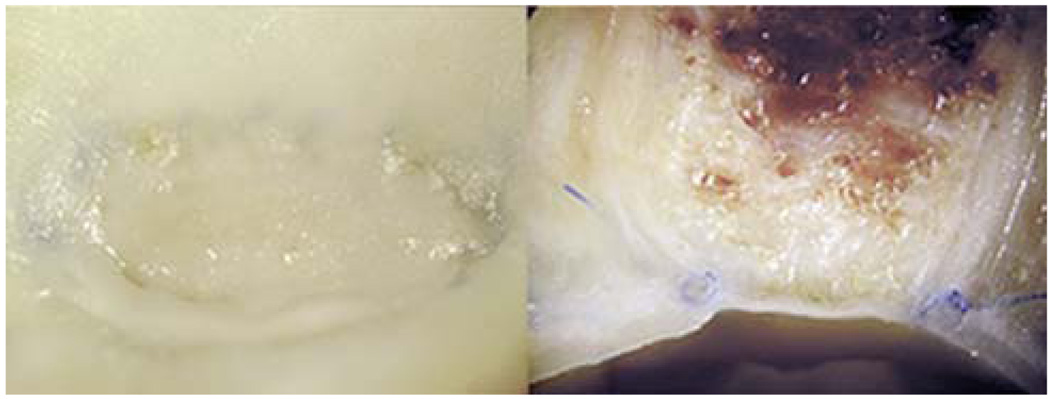
Macroscopic photographs of a dog lateral wall common carotid aneurysm embolized with CHEM foam. (Left) “En face” view of the aneurysm neck and (right) axial section image show complete aneurysm occlusion with good neointimal formation across the neck. (Reprinted with permission from A. Metcalfe, A. Desfaits, I. Salazkin, L. Yahia, W. M. Sokolowski and J. Raymond, Cold hibernated elastic memory foams for endovascular interventions, Biomaterials, 2003, 24, 491.55)
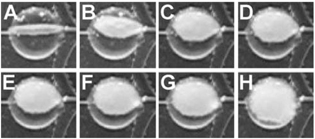
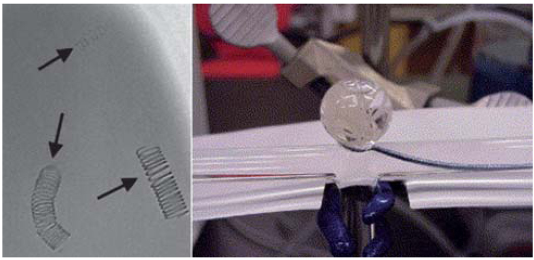
Temporal sequence of photothermal expansion of SMP foam in an in vitro aneurysm model. The aneurysm sac is located at the bifurcation of the main vessel. (Reprinted with permission from D. J. Maitland, W. Small, IV, J. M. Ortega, P. R. Buckley, J. Rodriguez, J. Hartman, and T. S. Wilson, Prototype laser-activated shape memory polymer foam device for embolic treatment of aneurysms, J. Biomed. Opt., 2007, 12, 030504.71)
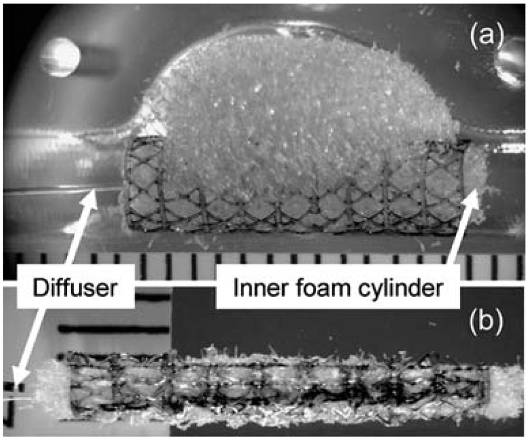
SMP stent-foam device with removable inner foam cylinder and laser light diffuser (a) before and (b) after collapsing for delivery. The device is shown in the bottom mold of the fusiform aneurysm model in (a). Scale divisions are in millimetres. (Reprinted with permission from W. Small, IV, P. R. Buckley, T. S. Wilson, W. J. Benett, J. Hartman, D. Saloner and D. J. Maitland, Shape memory polymer stent with expandable foam: a new concept for endovascular embolization of fusiform aneurysms, IEEE Trans. Biomed. Eng., 2007, 54, 1157.37)
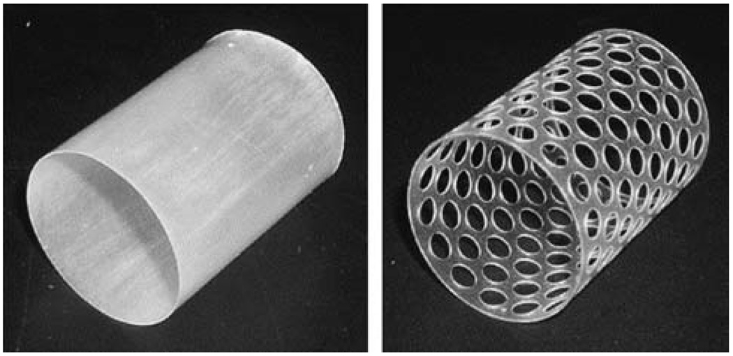
Design of solid and 50% perforated SMP stents. (Reprinted with permission from C. M. Yakacki, R. Shandas, C. Lanning, B. Rech, A. Eckstein and K. Gall, Unconstrained recovery characterization of shape-memory polymer networks for cardiovascular applications, Biomaterials, 2007, 28, 2255.86)
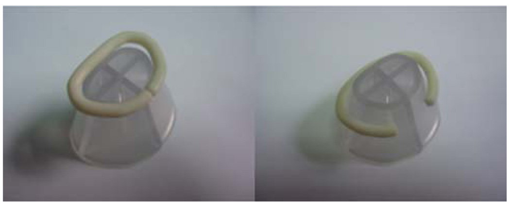
SMP annuloplasty ring shown in its (left) primary and (right) temporary forms. The ring is shown on the base used to set the temporary shape. (Reprinted with permission from A. D. Lantada, P. LaFont, I. Rada, A. Jimenez, J. L. Hernandez, H. Lorenzo-Yustos, and J. Munoz-Garcia, Active Annuloplasty System for Mitral Valve Insufficiency, in BIOSTEC 2008, CCIS 25, ed. A. Fred, J. Filipe and H. Gamboa, Springer-Verlag, Berlin, 2008, pp. 59–72.91)
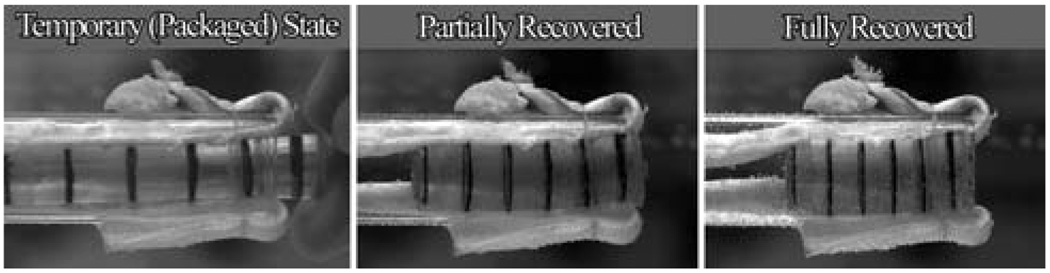
Demonstration of shape memory polymer cylindrical device expanding for soft tissue fixation. Note: black lines were drawn for visualization. (Reprinted with permission from C. M. Yakacki, R. Shandas, D. Safranski, A. M. Ortega, K. Sassaman and K. Gall, Strong, tailored, biocompatible shape-memory polymer networks, Adv. Funct. Mater., 2008, 18, 2428.59)
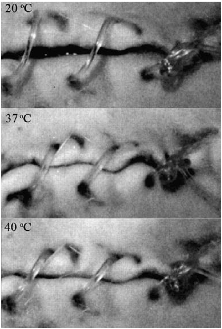
Biodegradable SMP suture for wound closure. The photoseries from the animal experiment shows the shrinkage of the suture as temperature increases. (Reprinted with permission from A. Lendlein and R. Langer, Biodegradable, elastic shape-memory polymers for potential biomedical applications, Science, 2002, 296, 1673.12)
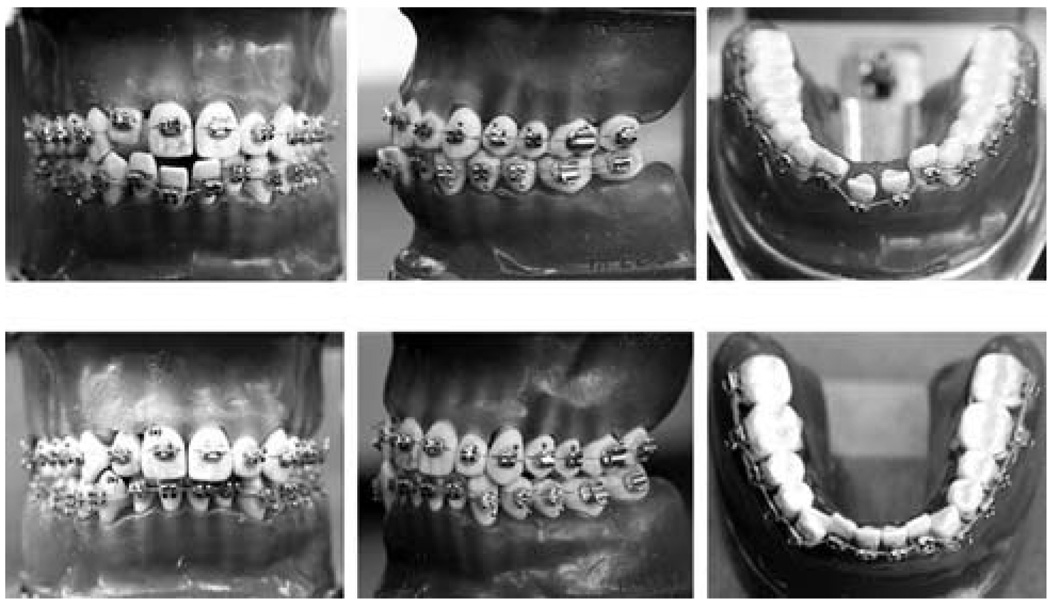
Photographs of the orthodontic appliance (top) before and (bottom) after treatment. The movement of the misaligned teeth due to a lateral force originating from the shape recovery of the SMP arch wire is seen. (Reprinted with permission from Y. C. Jung and J. W. Cho, J. Mater. Sci. Mater. Med., 2008, 1–6.111)
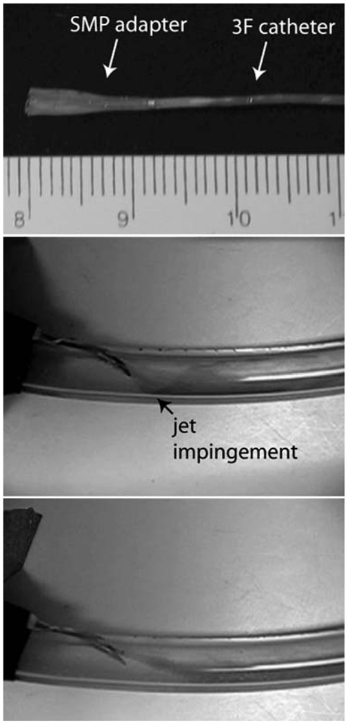
(Top) SMP adapter (in primary expanded form) mounted on a catheter for insertion into the dialysis needle (scale divisions in millimetres). Flow visualization within the AV graft model (middle) without and (bottom) with the SMP adapter. Jet impingement from the needle on the graft wall (black arrow) is evident when the adapter is not used. (Reprinted with permission from J. M. Ortega, W. Small, IV, T. S. Wilson, W. J. Benett, J. M. Loge and D. J. Maitland, A shape memory polymer dialysis needle adapter for the reduction of hemodynamic stress within arteriovenous grafts, IEEE Trans. Biomed. Eng., 2007, 54, 1722–1724.115)
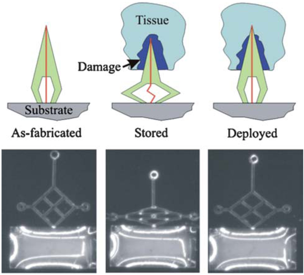
(Top) Schematic representation of the SMP neuronal probe actuator. The probe is fabricated with an enclosed conductor (vertical line) and deformed into a “crouched” conformation. It is then inserted surgically into the brain, resulting in an inflammatory response around the probe (damage). The heat from the body then causes slow actuation of the SMP probe back to its original conformation and moves the probe tip beyond the zone of tissue damage created by implantation. (Bottom) Light micrograph of a prototype SMP probe. The first panel shows a light micrograph of the as-fabricated prototype SMP probe. The middle panel shows the deformed or “crouched” configuration of the probe after it was stretched horizontally. The final panel shows the recovered conformation after deployment at 37 °C. (Reprinted with permission from A.A. Sharp,H.V. Panchawagh, A. Ortega, R. Artale, S. Richardson-Burns, D. S. Finch, K. Gall, R. L. Mahajan and D. Restrepo, Toward a self-deploying shape memory polymer neuronal electrode, J. Neural Eng., 2006, 3, 23–30.117)
References
-
- El Feninant F, Laroche G, Fiset M, Mantovani D. Adv. Eng. Mater. 2002;4:91–104.
-
- Sokolowski W, Metcalfe A, Hayashi S, Yahia L, Raymond J. Biomed. Mater. (Bristol, U. K.) 2007;2:S23–S27. - PubMed
-
- Lendlein A, Kelch S. Angew. Chem., Int. Ed. 2002;41:2034–2057. - PubMed
-
- Liu C, Qin H, Mather PT. J. Mater. Chem. 2007;17:1543–1558.
Grants and funding
LinkOut - more resources
Full Text Sources
Other Literature Sources