. 2011 Apr 15;197(1):32-47.
doi: 10.1016/j.jneumeth.2011.01.024. Epub 2011 Feb 1.

Analyzing the dynamics of brain circuits with temperature: design and implementation of a miniature thermoelectric device

Affiliations

Analyzing the dynamics of brain circuits with temperature: design and implementation of a miniature thermoelectric device

Dmitriy Aronov et al. J Neurosci Methods. .

Abstract

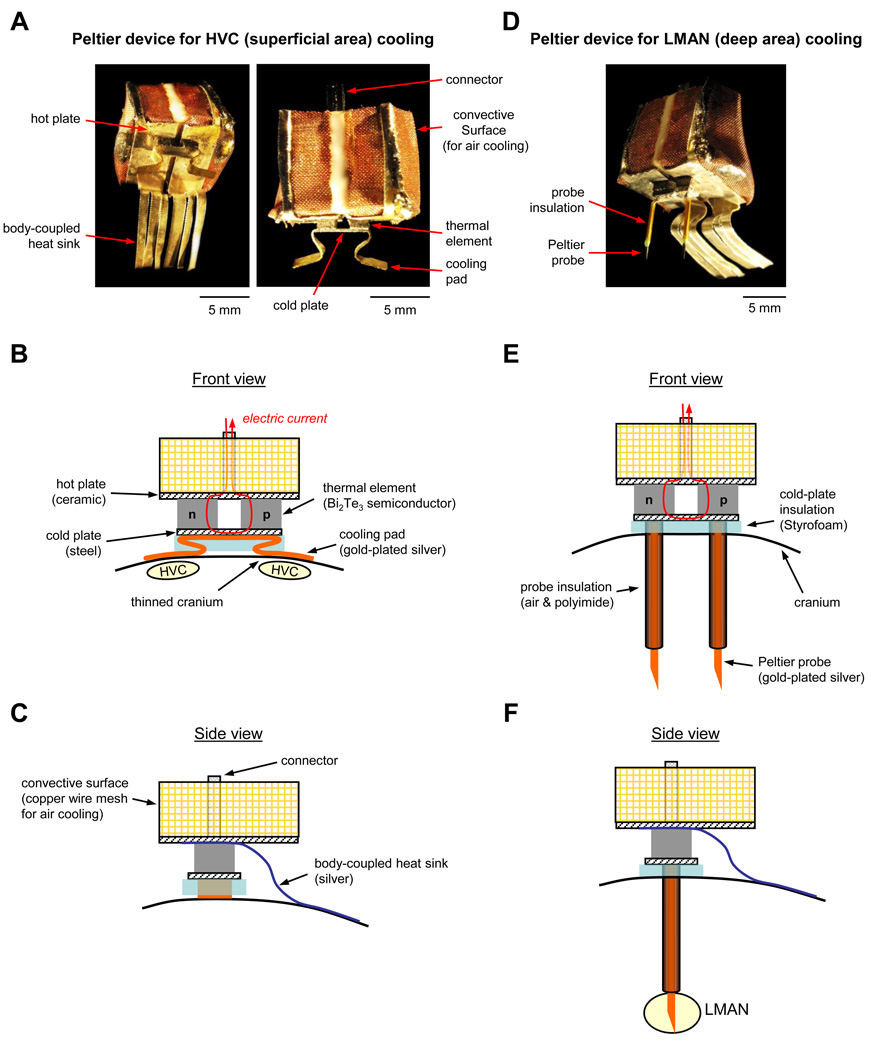
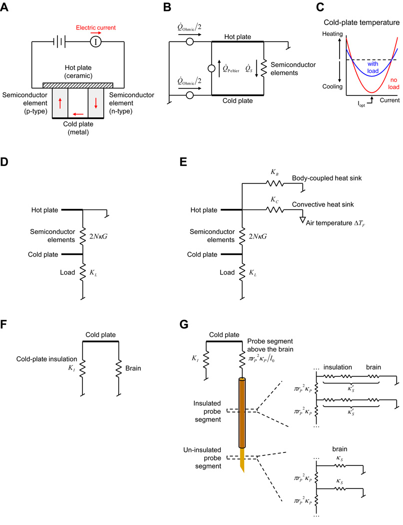
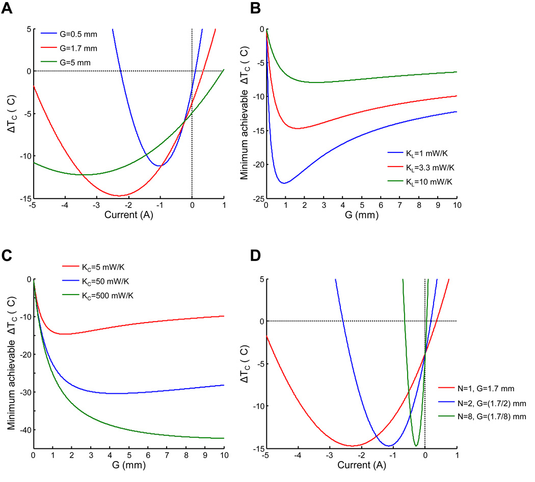
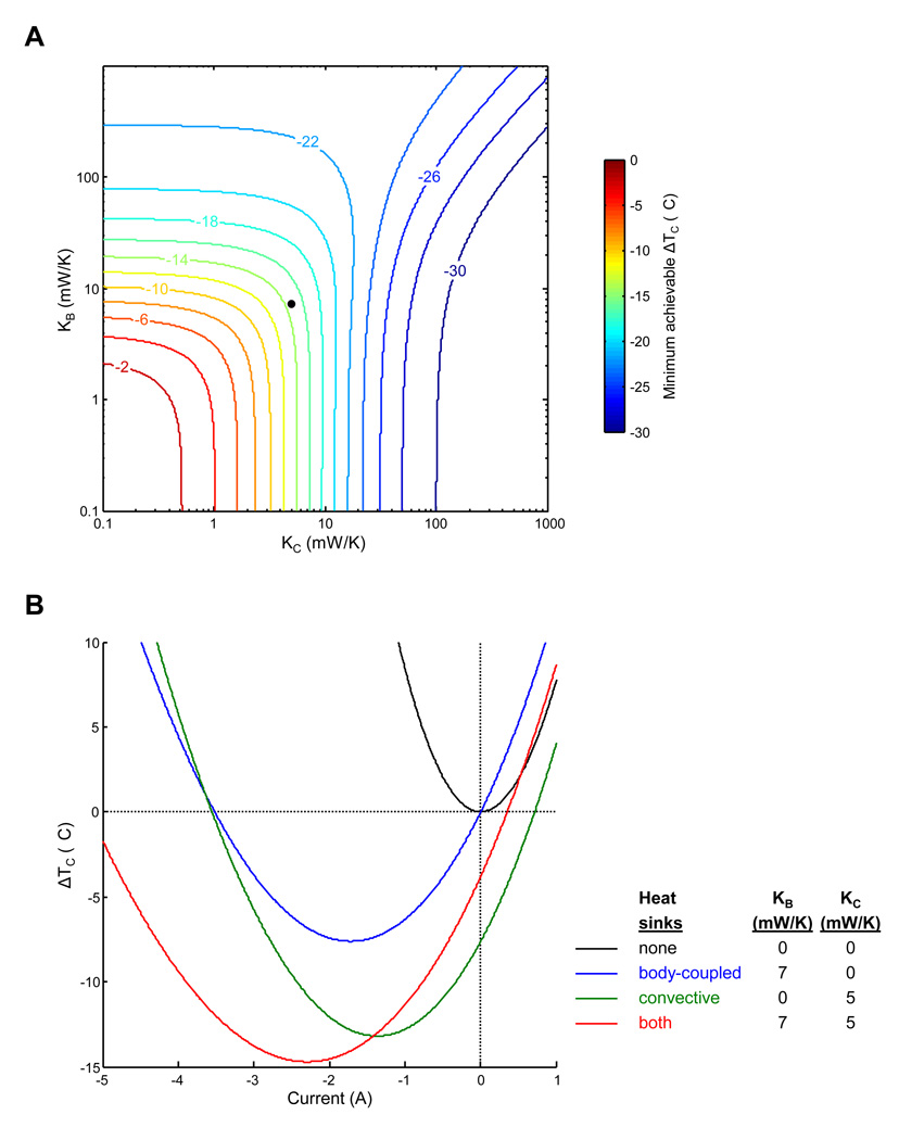
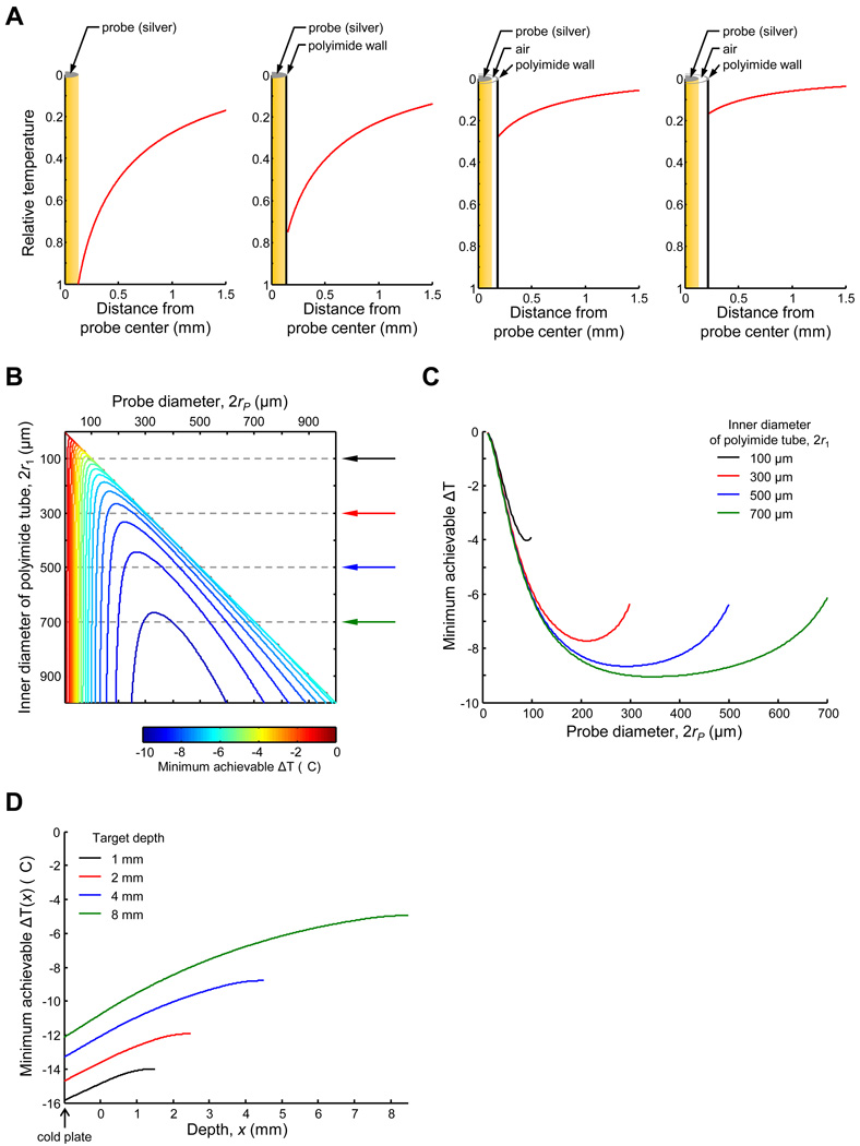
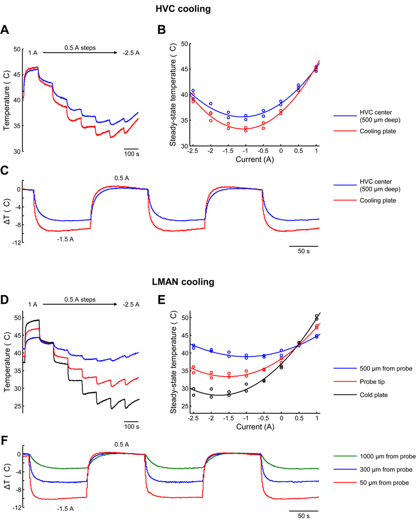
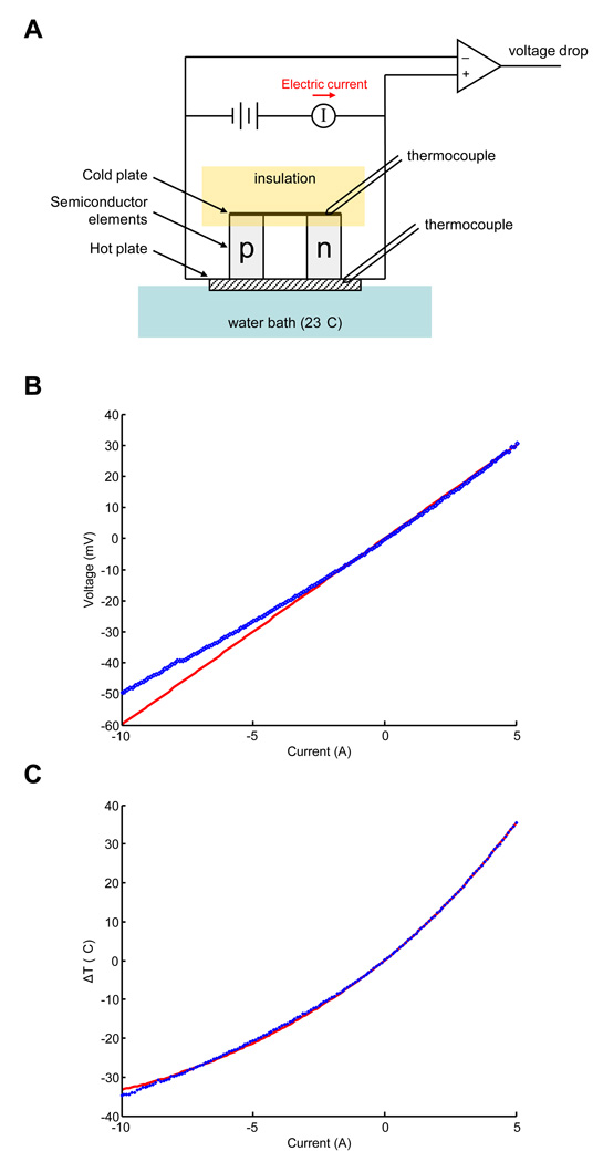
Traditional lesion or inactivation methods are useful for determining if a given brain area is involved in the generation of a behavior, but not for determining if circuit dynamics in that area control the timing of the behavior. In contrast, localized mild cooling or heating of a brain area alters the speed of neuronal and circuit dynamics and can reveal the role of that area in the control of timing. It has been shown that miniaturized solid-state heat pumps based on the Peltier effect can be useful for analyzing brain dynamics in small freely behaving animals (Long and Fee, 2008). Here we present a theoretical analysis of these devices and a procedure for optimizing their design. We describe the construction and implementation of one device for cooling surface brain areas, such as cortex, and another device for cooling deep brain regions. We also present measurements of the magnitude and localization of the brain temperature changes produced by these two devices.


Figures

Figure 1
Figure 1. Implementation of two Peltier-based thermoelectric devices for localized brain cooling
(A) Photograph of the device for cooling a structure located close to the surface of the brain (nucleus HVC in the songbird) using cooling pads placed against thinned areas of the cranium. (B–C) Schematics of the device shown in (a). (D) Photograph of the device for cooling a structure deep in the brain (nucleus LMAN in the songbird) using thermally conductive probes. (E–F) Schematics of the device shown in (D). Abbreviations: HVC, used as a proper name, formerly high vocal center; LMAN, lateral magnocellular nucleus of the nidopallium.
Figure 2
Figure 2. Analysis of the thermoelectric device using equivalent thermal circuits
(A) Schematic of a device. Electric current flows back-and-forth between the hot and the cold plates along semiconductor elements. For one direction of current flow, the Peltier effect cools the cold plate and heats up the hot plate. One semiconductor pair (N=1) is shown. The device is attached to a perfect heat sink, represented by “grounding” the hot plate. (B) Equivalent thermal circuit for the device shown in (A). Semiconductor elements are represented by a thermal conductance. Heat is pumped from the cold plate due to the Peltier effect (Peltier). Ohmic heat from the current flow (Ohmic) is transferred equally to each of the plates. (C) Plot of the steady-state temperature achieved at the cold plate for an isolated device and for the same device attached to a thermal load. Optimal cooling is achieved at current Iopt. (D) Equivalent circuit for a device attached to a load, represented by a conductance KL . (E) Equivalent circuit of a device with non-ideal heat sinks represented by conductances: KB is a body-coupled heat sink; KC is a convective heat sink, cooled by a fluid of temperature ΔTF relative to body temperature. (F) Equivalent circuit of the load on the cold plate in the planar geometry. Insulation is represented by a thermal conductance KI in parallel with the brain. (G) Equivalent circuit of the load on the cold plate in cylindrical geometry. Only one probe is shown. The probe has axial thermal conductivity (vertical resistors) that depends on its radius rP and material conductivity κP . Segments within the brain also have substantial surface conductivity κS for the un-insulated segment and κS for the insulated one), expressed per unit length of the probe.
Figure 3
Figure 3. Influence of semiconductor geometry on device performance
(A) Steady-state temperature of the cold plate ΔTC as a function of current flow through the device, for three values of the geometric constant G. Geometric constant of the semiconductor elements affect the minimum-achievable temperature. (B) Minimum achievable ΔTC as a function of G, for different values of the thermal load. For the load conductance estimated for our device (3.3 milliwatts per Kelvin, mW/K), the lowest temperature is achieved for G ≈ 1.7mm (red trace). Note that lower values of G are optimal for smaller loads. (C) Relationship between the minimum achievable ΔTC and G for different conductances of the convective heat sink, KC . Larger values of G are optimal for more efficient heat sinks. (D) Relationship between ΔTC and current for three devices with different numbers of semiconductor junctions (N). For each device, the value of G is scaled by N such that the overall surface area of the semiconductors remains the same. Devices with more semiconductor junctions achieve identical temperatures at the cold plate, but less current is required to achieve the minimum temperature.
Figure 4
Figure 4. Influence of heat sinks on device performance
(A) Minimum steady-state temperature achievable at the cold plate, ΔTC as a function of two heat sink conductances: the body-coupled heat sink KB and the convective heat sink KC . At small conductance values, improving either heat sink improves the minimum achievable temperature at the cold plate. However, when the convective heat sink is efficient (>~20 milliwatts per Kelvin, mW/K), attaching a body-coupled heat sink does not improve performance. Contours are spaced at intervals of 2°C; numbers indicate ΔTC in °C. Black symbol indicates heat sink values of our “core” device (see text). (B) Effects of including or omitting small body-coupled (7 mW/K) and convective (5 mW/K) heat sinks. For each combination of heat sinks, the steady-state temperature at the cold plate is shown as a function of device current. The lowest temperature is achievable when both heat sinks are included (red trace). Including both heat sinks, in addition to improving the maximum cooling of the device compared convective heat sink alone (green trace), substantially reduces the amount of unwanted cooling at zero current.
Figure 5
Figure 5. Optimizing probe insulation for cooling deep brain structures
(A) Effectiveness of various probe insulations in the brain. Leftmost plot shows the spatial profile (red trace) of the steady-state temperature in the brain near an un-insulated probe. The three rightmost plots shown this profile for probes insulated with a polyimide tube (25 µm-thick wall), with different amounts of air insulation (0, 35, and 75 µm) between the probe and the polyimide tube. (B) Minimum temperature achievable in the brain (2 mm deep, 200 µm from the central axis of the probe), for different dimensions of the probe and the insulation. For each configuration, the polyimide wall is 25 µm thick and the space between the probe surface and the inner polyimide wall is filled with air. Contours are spaced at intervals of 0.5°C. (C) Effects of varying probe diameter while holding the polyimide tube diameter fixed. Traces are shown for four different diameters of polyimide tube. For each polyimide tube diameter, an optimum probe diameter exists. (D) Temperature profile along the length of the probe, for various probe lengths. For each probe, the initial 1-mm segment is above the brain (and effectively ideally insulated by being embedded in Styrofoam) and the final 1-mm segment is un-insulated, such that the targeted depth is at the center of the un-insulated segment. The rest of the probe is insulated with polyimide tubing.
Figure 6
Figure 6. Measurements of temperature produced by thermoelectric devices
(A) Temperature at the cooling plate and in HVC at various amounts of current flown through the HVC cooling device. The amount of current is changed every 100 s, decreasing from 1 to −2.5 A in steps on 0.5 A. (B) Steady-state temperature as a function of current at the two locations. Steady-state is estimated by fitting an exponential curve to the last 70 s of each current step in (A). (C) Temperature at the same two locations during an experiment in which current is alternated between 0.5 and −1.5 A every 100 s. (D,E) Temperatures at the cold plate of the LMAN cooling device, at the probe tip, and at 500 µm away from the surface of the probe. Data are estimated and plotted as in (A,B). (F) Temperature at three distances from the probe surface of the LMAN cooling device during alternation of the current between 0.5 and −1.5 A every 100 s, as in (C).
Figure A1
Figure A1. (In Appendix A) Estimation of semiconductor properties
(A) Schematic of the experimental setup. The hot plate of the Peltier device is maintained at a near-constant temperature using a large water bath; the cold-plate is insulated with Styrofoam. The temperature difference, ΔT, between the hot and cold plates is measured with small thermocouples. A constant current pulse (90 s duration) is applied to the device, and an instrumentation amplifier is also used to record the voltage drop across the semiconductor elements. (B) Average steady-state voltage across the device at different values of current (blue symbols). The red line is a linear fit to the data in the range from (25–42°C). Note that the data deviate from the linear fit, likely due to the temperature-dependence resistance of the semiconductor material. (C) Average steady-state temperature difference between the hot and the cold plates at different current levels (blue symbols). A quadratic fit to the data is shown (red curve), from which the Seebeck coefficient and thermal conductivity of the semiconductor elements were estimated.

Similar articles

Cited by

References

    1. Abeles M. Corticonics. Cambridge University Press; 1991.
    1. Arbas EA, Calabrese RL. Rate modification in the heartbeat central pattern generator of the medicinal leech. J Comp Physiol A. 1984;155:783–794.
    1. Ashmore RC, Wild JM, Schmidt MF. Brainstem and forebrain contributions to the generation of learned motor behaviors for song. J. Neurosci. 2005;25:8543–8554. - PMC - PubMed
    1. Bauer M, von Helversen O. Separate localization of sound recognizing and sound producing neural mechanisms in a grasshopper. J Comp Physiol A. 1987;161:95–101.
    1. Bech C, Midtgård U. Brain temperature and therete mirabile ophthalmicum in the Zebra finch (Poephila guttata) J Comp Physiol B. 1981;145:89–93.

LinkOut - more resources