

The crystal structure of the signal recognition particle in complex with its receptor
- PMID: 21330537
- PMCID: PMC3758919
- DOI: 10.1126/science.1196473
The crystal structure of the signal recognition particle in complex with its receptor
Abstract
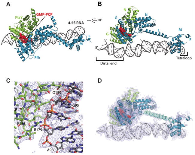
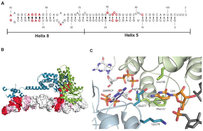
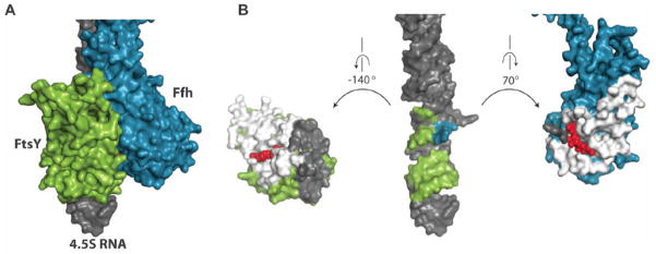
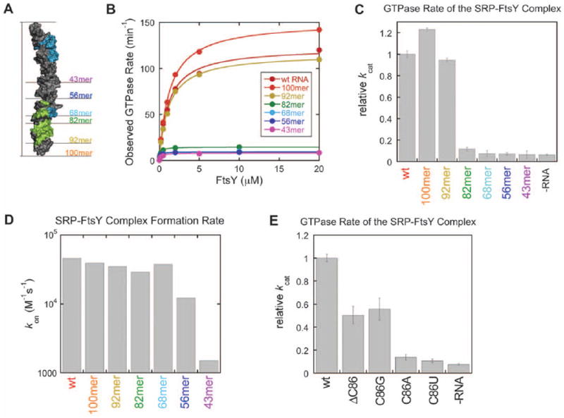
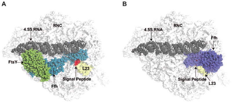
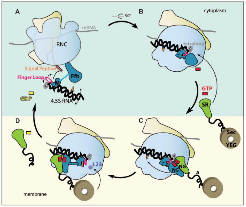
Cotranslational targeting of membrane and secretory proteins is mediated by the universally conserved signal recognition particle (SRP). Together with its receptor (SR), SRP mediates the guanine triphosphate (GTP)-dependent delivery of translating ribosomes bearing signal sequences to translocons on the target membrane. Here, we present the crystal structure of the SRP:SR complex at 3.9 angstrom resolution and biochemical data revealing that the activated SRP:SR guanine triphosphatase (GTPase) complex binds the distal end of the SRP hairpin RNA where GTP hydrolysis is stimulated. Combined with previous findings, these results suggest that the SRP:SR GTPase complex initially assembles at the tetraloop end of the SRP RNA and then relocalizes to the opposite end of the RNA. This rearrangement provides a mechanism for coupling GTP hydrolysis to the handover of cargo to the translocon.
Figures
Similar articles
-
Molecular mechanism of GTPase activation at the signal recognition particle (SRP) RNA distal end.J Biol Chem. 2013 Dec 20;288(51):36385-97. doi: 10.1074/jbc.M113.513614. Epub 2013 Oct 22. J Biol Chem. 2013. PMID: 24151069 Free PMC article.
-
RNA-mediated interaction between the peptide-binding and GTPase domains of the signal recognition particle.Nat Struct Mol Biol. 2005 Dec;12(12):1116-22. doi: 10.1038/nsmb1025. Epub 2005 Nov 20. Nat Struct Mol Biol. 2005. PMID: 16299512
-
The signal recognition particle (SRP) RNA links conformational changes in the SRP to protein targeting.Mol Biol Cell. 2007 Jul;18(7):2728-34. doi: 10.1091/mbc.e07-02-0117. Epub 2007 May 16. Mol Biol Cell. 2007. PMID: 17507650 Free PMC article.
-
Structural insights into the signal recognition particle.Annu Rev Biochem. 2004;73:539-57. doi: 10.1146/annurev.biochem.73.011303.074048. Annu Rev Biochem. 2004. PMID: 15189152 Review.
-
A tale of two GTPases in cotranslational protein targeting.Protein Sci. 2011 Nov;20(11):1790-5. doi: 10.1002/pro.729. Epub 2011 Sep 27. Protein Sci. 2011. PMID: 21898651 Free PMC article. Review.
Cited by
-
RNA Structures as Mediators of Neurological Diseases and as Drug Targets.Neuron. 2015 Jul 1;87(1):28-46. doi: 10.1016/j.neuron.2015.06.012. Neuron. 2015. PMID: 26139368 Free PMC article. Review.
-
ATP-association to intrabacterial nanotransportation system in Vibrio cholerae.Med Mol Morphol. 2015 Dec;48(4):225-34. doi: 10.1007/s00795-015-0105-4. Epub 2015 May 19. Med Mol Morphol. 2015. PMID: 25986680
-
Analyzing Single-Molecule Protein Transportation Experiments via Hierarchical Hidden Markov Models.J Am Stat Assoc. 2016;111(515):951-966. doi: 10.1080/01621459.2016.1140050. Epub 2016 Oct 18. J Am Stat Assoc. 2016. PMID: 28943680 Free PMC article.
-
Base pair probability estimates improve the prediction accuracy of RNA non-canonical base pairs.PLoS Comput Biol. 2017 Nov 6;13(11):e1005827. doi: 10.1371/journal.pcbi.1005827. eCollection 2017 Nov. PLoS Comput Biol. 2017. PMID: 29107980 Free PMC article.
-
Two-step membrane binding by the bacterial SRP receptor enable efficient and accurate Co-translational protein targeting.Elife. 2017 Jul 28;6:e25885. doi: 10.7554/eLife.25885. Elife. 2017. PMID: 28753124 Free PMC article.
References
-
- Keenan RJ, Freymann DM, Stroud RM, Walter P. The signal recognition particle. Annu Rev Biochem. 2001;70:755. - PubMed
-
- Doudna JA, Batey RT. Structural insights into the signal recognition particle. Annu Rev Biochem. 2004;73:539. - PubMed
-
- Batey RT, Rambo RP, Lucast L, Rha B, Doudna JA. Crystal structure of the ribonucleoprotein core of the signal recognition particle. Science. 2000 Feb 18;287:1232. - PubMed
-
- Egea PF, et al. Substrate twinning activates the signal recognition particle and its receptor. Nature. 2004 Jan 15;427:215. - PubMed
Publication types
MeSH terms
Substances
Associated data
- Actions
Grants and funding
LinkOut - more resources
Full Text Sources
Other Literature Sources
Molecular Biology Databases
Research Materials
