. 2011 Apr;65(4):927-48.
doi: 10.1002/mrm.22761. Epub 2011 Feb 17.

Chemical exchange saturation transfer (CEST): what is in a name and what isn't?

Affiliations

Chemical exchange saturation transfer (CEST): what is in a name and what isn't?

Peter C M van Zijl et al. Magn Reson Med. 2011 Apr.

Abstract

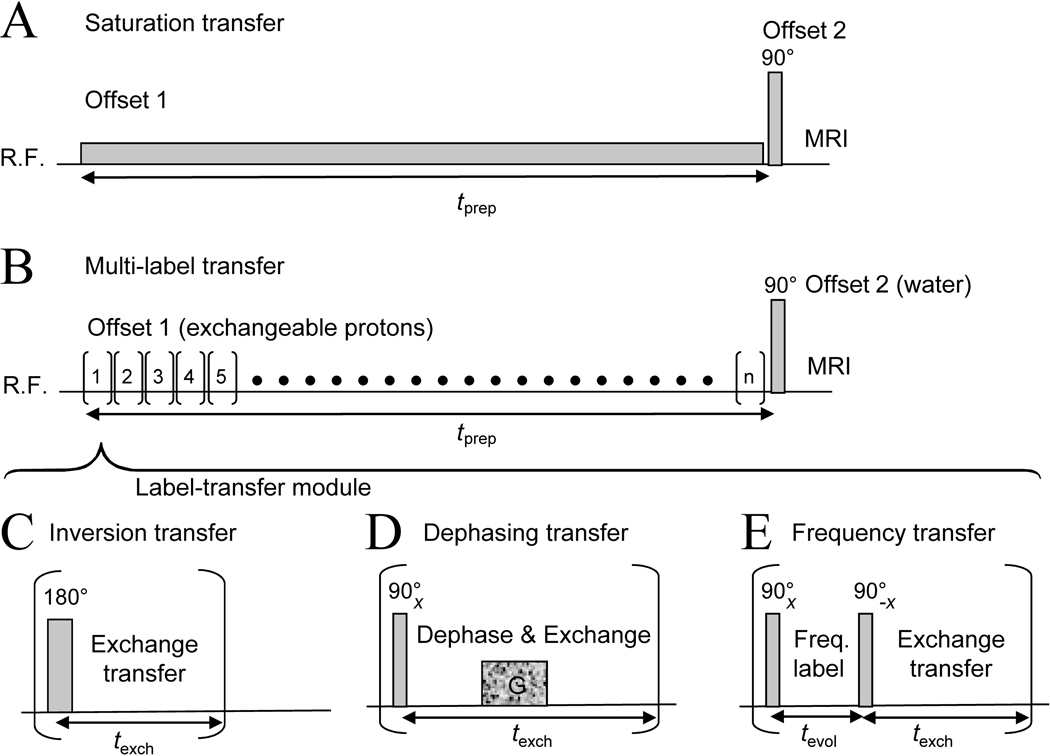
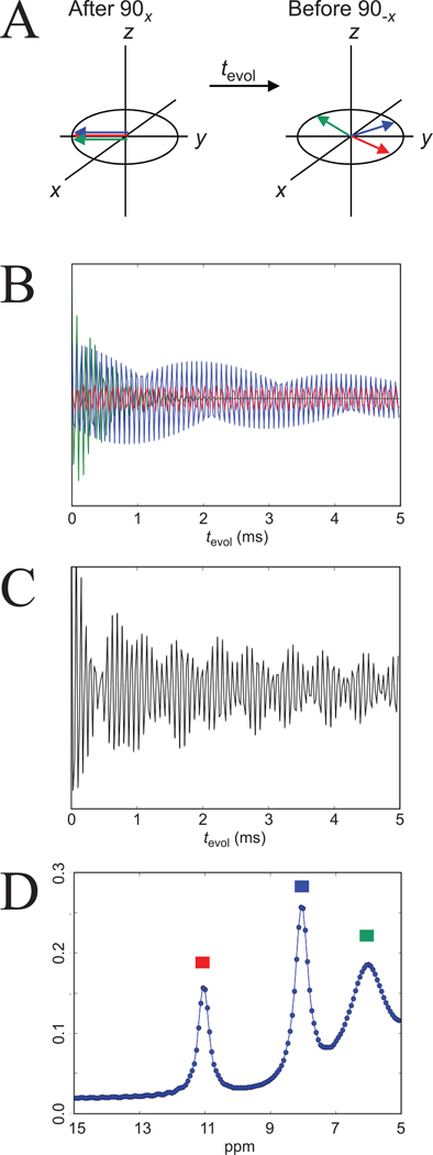
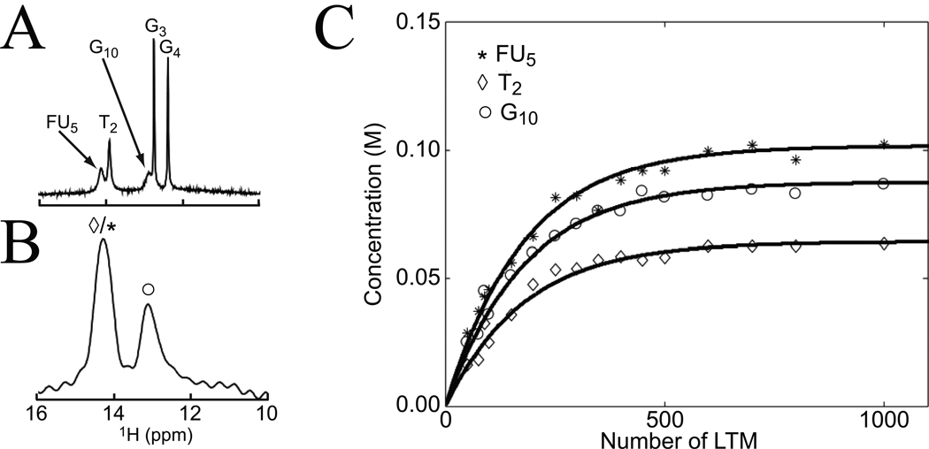
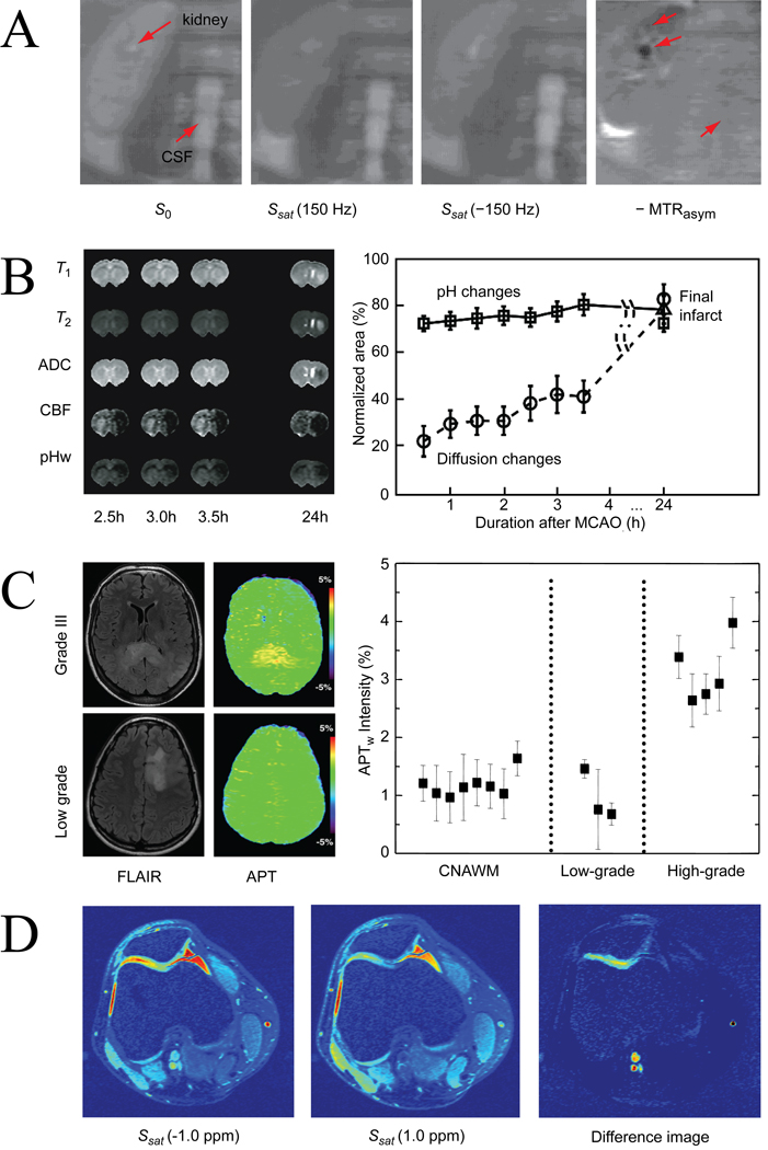
Chemical exchange saturation transfer (CEST) imaging is a relatively new magnetic resonance imaging contrast approach in which exogenous or endogenous compounds containing either exchangeable protons or exchangeable molecules are selectively saturated and after transfer of this saturation, detected indirectly through the water signal with enhanced sensitivity. The focus of this review is on basic magnetic resonance principles underlying CEST and similarities to and differences with conventional magnetization transfer contrast. In CEST magnetic resonance imaging, transfer of magnetization is studied in mobile compounds instead of semisolids. Similar to magnetization transfer contrast, CEST has contributions of both chemical exchange and dipolar cross-relaxation, but the latter can often be neglected if exchange is fast. Contrary to magnetization transfer contrast, CEST imaging requires sufficiently slow exchange on the magnetic resonance time scale to allow selective irradiation of the protons of interest. As a consequence, magnetic labeling is not limited to radio-frequency saturation but can be expanded with slower frequency-selective approaches such as inversion, gradient dephasing and frequency labeling. The basic theory, design criteria, and experimental issues for exchange transfer imaging are discussed. A new classification for CEST agents based on exchange type is proposed. The potential of this young field is discussed, especially with respect to in vivo application and translation to humans.


Figures

Figure 1
Figure 1. Chemical Exchange Saturation Transfer (CEST): principles and measurement approach for pure exchange effects
(A, B) Solute protons (blue) are saturated at their specific resonance frequency in the proton spectrum (here 8.25 ppm for amide protons). This saturation is transferred to water (4.75 ppm) at exchange rate ksw and non-saturated protons (black) return. After a period (tsat), this effect becomes visible on the water signal (B, right). (C) Measurement of normalized water saturation (Ssat/S0) as a function of irradiation frequency, generating a so-called Z-spectrum (or CEST spectrum or MT spectrum). When irradiating the water protons at 4.75 ppm, the signal disappears due to direct (water) saturation (DS). This frequency is assigned to 0 ppm in Z-spectra. At short saturation times, only this direct saturation is apparent. At longer tsat the CEST effect becomes visible at the frequency of the low-concentration exchangeable solute protons, now assigned to 8.25 − 4.75 = 3.5 ppm in the Z-spectrum. (D) Result of Magnetization Transfer Ratio (MTR = 1 – Ssat/S0) asymmetry analysis of the Z-spectrum with respect to the water frequency to remove the effect of direct saturation. In the remainder of this paper we will use the standard NMR chemical shift assignment for water at 4.75 ppm in 1H spectra, while the 0 ppm assignment will be used in Z-spectra.
Figure 2
Figure 2. Effect of exchange regime on proton spectra versus CEST spectra for a solution of 200 mM glycogen
(A) 1H NMR spectra acquired at 9.4 T in unbuffered H2O (pH = 7) as a function of temperature. The OH resonances at 1.2 ppm and 0.7 ppm (2:1 ratio) from water broaden at higher temperature, where exchange is faster. (B) The corresponding CEST-spectra show increased glycogen detectability at higher temperature. (C) CEST-spectra in PBS buffer (37°C, pH = 7.4) acquired at 9.4 T and 4.7 T using tsat = 10 s, B1 = 1.9 µT. Notice the better definition of the CEST effect at higher field due to the increased chemical shift difference with water. Reproduced, with permission, from van Zijl et al., Proc. Natl. Acad. Sci. USA 2007;104:4359–4364. Copyright (2007) National Academy of Sciences, USA.
Figure 3
Figure 3. Classification of CEST contrast based on exchange type
(A) Proton exchange: magnetic labeling of exchangeable protons, which is the case for most diamagnetic CEST (DIACEST) compounds reported until now and several paramagnetic (PARACEST) agents. As an example, hydroxyl, amide and amine protons in a peptide are shown. SupraCEST relates to paramagnetic agents that are coordinated to macromolecular units in which the exchangeable side group protons are studied (113). (B) Molecular exchange: magnetic labeling of exchangeable molecules, in this case a water molecule coordinated to Europium in a PARACEST agent. For these agents, the molecular exchange rate is generally faster than the proton-proton exchange rate. (C). Compartmental exchange: Magnetic labeling of compartmentalized water molecules in a fast-exchange environment resulting in a single average resonance frequency for compartmental water that is different from bulk water. This shift can be induced by either a paramagnetic or diamagnetic agent locked into the compartment or by changing the shape of the compartment to induce a bulk magnetic susceptibility (BMS) anisotropy. The shift difference allows selective irradiation of the compartmental pool. Due to the large size of the irradiated water pool and the fact that the effect spreads beyond the liposome, giga-size enhancements can be induced (Table 1). Fig. B was provided by Mark Woods, Portland State University, Portland.
Figure 4
Figure 4. Factors affecting detectability for the main classes of CEST agents
(A) Effects of exchange rate (log plot) and radiofrequency field B1 on the saturation efficiency (Eq. [4]) for the B1 range typically used on clinical scanners for SAR-compatible saturation experiments. Saturation transfer efficiency reduces with increased exchange rate, which can only be overcome by increasing B1. (B) Dependence of the product of saturation transfer efficiency and exchange rate on ksw and B1, showing that the increase in rate sufficiently compensates for the lost efficiency at clinically reasonable power levels. (C) Log-plot of concentrations needed to achieve a 5% CEST effect for the different groups of agents. Notice that the curves for proton exchange and molecular exchange agents are affected by molecular size, while the compartmental exchange curve depends on particle radius, affecting both exchange rate and number of protons. Also, it is important to realize that paraCEST agents can be found in all three classes and water is normally the solvent, which is why we used para-H2O to indicate molecular exchange. Graph is only approximate and meant to provide rough guideline.
Figure 5
Figure 5. Z-spectra for glycosaminoglycans (GAGs) in solution and in cartilage showing CEST and cross-relaxation effects
(PBS, 11.7 T, tsat = 4 s, 2.35 µT, 37 °C). (A) structure of GAG-unit, showing three OH groups, an amide proton and several aliphatic protons in the ring (CH) and the N-Acetyl side chain. (B) Z-spectra of 125 mM GAG units in solution, showing predominantly NH and OH exchange saturation transfer effects. (C) Z-spectra of cartilage from bovine patella in PBS buffer showing exchange and much increased cross-relaxation (nuclear Overhauser enhancement (NOE)) effects. Adapted from and reproduced with permission from Ling et al., Proc. Natl. Acad. Sci. USA 2008;105:2266–2270. Copyright (2008) National Academy of Sciences, USA.
Figure 6
Figure 6. Illustration of magnetization transfer pathways in proteins
(A) Possible pathways in a mobile protein during a water exchange (WEX) experiment consisting of selective magnetic labeling (inversion) of bulk water (inverse of CEST/MT approaches) followed by a waiting period. Chemical exchange (red) and cross relaxation (blue) occur, the latter either exchange-relayed or through direct excitation of C(α) protons. These pathways are seen in cancer cells (B) as well as rat brain (C), showing fast buildup of exchangeable proton signals (especially amide protons at 8.25 ppm) as a function of time after inversion followed by gradual transfer to aliphatic protons through intramolecular NOEs. (D) Transfer processes occurring during an MTC experiment. The semi-solid matrix, where fast intramolecular dipolar transfer occurs, is indicated in grey. Contrary to mobile proteins, the effects of both exchange and intermolecular NOEs with bound water can be substantial. Adapted, with permission, from van Zijl et al., Magn. Reson. Med. 2003;49:440–449.
Figure 7
Figure 7. Effect of MTC on Z-spectra and CEST data analysis for 9L glioma (A-C) and ischemia (D-F) in rat brain
(Multi-pulse saturation: 400 Gaussian 180° pulses, 4.7 T, tsat = 4 s, B1 = 1.2 µT). Solid circle: contralateral brain; diamond: peritumoral tissue (A-C); open circle: tumor (A-C) or ischemic lesion (D-F). Signal attenuation in Z-spectra (A, D) is due mainly to direct water saturation close to the water frequency and a large MTC effect (~ 40–60%) over the whole spectral range. The MTC contribution is reduced for edema and tumor (A), indicating a higher water content for these tissues. The Z-spectra are slightly asymmetric, which becomes visible when performing asymmetry analysis (B, E). Both exchange effects and asymmetry in the MTC contribute to the residual curve, with the latter reflected in a relatively constant negative MTRasym (2–3%) at offsets above 5 ppm. The PTR for tissue changes can be estimated by comparing lesion with normal brain, removing most of the MTC effects (C, F). This shows that edematous regions can be separated from tumor (C) and ischemia from normal brain (F). The positive (C) and negative (F) PTR differences were attributed to increases in protein content and reduced pH, respectively. Adapted, with permission from Zhou et al., Magn. Reson. Med. 2003;50:1120–1126 (A-C) and Nat. Med. 2003;9:1085–1090 (D-F).
Figure 8
Figure 8. Possible schemes for exchange transfer MRI
(A) Standard CEST: protons are labeled through continuous saturation and transferred continuously during labeling. (B) Exchange transfer using label-transfer modules (LTMs): protons are rapidly labeled through either selective inversion (C) or selective excitation followed by a magnetic manipulation (D, E). This can be gradient dephasing (D) or frequency labeling during an evolution time tevol followed by selective flipback to the z-axis (E). After labeling, exchange transfer to water protons occurs during texch. The label transfer modules, (n total), are repeated continuously during preparation period tprep to enhance the effect on bulk water. The water labeling efficiency depends on the exchange rate, which, together with the power deposition limits, determines the number of modules that can be used.
Figure 9
Figure 9. Principle of frequency labeled exchange transfer (FLEX)
A range of frequencies including multiple exchangeable protons is selectively excited (90x pulse, Fig. 8E), after which chemical shift evolution separates the different frequency components (red, blue, green). Depending on tevol, a different size of magnetization component is flipped back to the z-axis by the 90-x pulse (A) and transferred to water protons. When performing a series of acquisitions at different evolution times, a free induction decay (FID) containing the multiple frequency components is obtained (B). These components are all part of a single water signal and non-distinguishable (C). However, Fourier transform of the convoluted decay can recover a frequency spectrum (D), allowing separation of the three different components based on frequency (chemical shift) and exchange rate (peak width). The normal 1H NMR spectral frequencies were used with water assigned to 4.75 ppm. Parameters used in B-D: field of 14.1 T (600 MHz); offset frequency of RF pulse 25 ppm from water; dwell time 25 µs. Signals were green: 20 mM, 6 ppm, k = 2000 Hz; blue: 10 mM, 8 ppm, k = 200 Hz; red: 5 mM, 11 ppm, k = 20 Hz. FID processed using 20 Hz exponential line broadening and zero filling by a factor of four. Courtesy of Josh Friedman, Johns Hopkins University.
Figure 10
Figure 10. Illustration of lipid interference and suppression in 3D amide proton transfer (APT) scanning in the human brain
3D Gradient and spin echo (GRASE) acquisition with multi-pulse saturation preparation showing saturated images at ± 3.5 ppm as well as the calculated MTRasym (3.5 ppm) images for three slices (in three columns) without and with lipid suppression. Without lipid suppression, ring-like hypointensities (white arrows) appear in the MTRasym (3.5 ppm) images, which are removed when applying a frequency-modulated selective lipid suppression pulse in both image acquisitions (± 3.5 ppm). Reproduced, with permission, from Zhu et al., Magn. Reson. Med. 2010;64:638–644.
Figure 11
Figure 11. Illustration of quantitative concentration determination using the FLEX method for the DNA duplex 5’-C1T2G3G4FU5A6C7C8A9G10-3’
(T = 10 °C; pH = 9.0; C = Cytosine; T = Thymidine; G = Guanosine; FU = Fluorouracil; A = Adenosine). (A) Conventional jump-return spectrum in which all imino protons are observable. (B) FLEX spectra in which G3 and G4 do not appear due to slow exchange. (C) Absolute concentration of labeled protons generated by FLEX as a function of the number of applied LTMs. Data based on time domain fitting using prior knowledge of the chemical shift and decay rate. Black lines are best fits of data to Eq. [10] (concentration = PTR · 2 · [H2O]). Reproduced, with permission from Friedman et al., J. Am. Chem. Soc. 2010;132:1813–1815.
Figure 12
Figure 12. In vivo CEST studies exploiting the presence of endogenous proton exchange agents
(A) Imaging of urea in kidney. Comparison of coronal images through the kidney of a normal volunteer kidney without saturation (S0), and with saturation (Ssat) applied symmetrically about the water frequency for the resonance frequency difference (+150 Hz at 1.5 T) of urea protons. The red arrows in the S0 image indicate the calyx in the kidney (urea collecting system) and CSF in the spinal cord, which is used as a reference. The asymmetry image on the right is inverse of current definition and therefore labeled as -MTRasym. This image is darker in the calyx (middle red arrow) and renal papillae (top arrow) while no differences are visible in CSF (bottom arrow). Reproduced, with permission, from Dagher et al., J. Magn. Reson. Imaging 2000;12:745–748. (B) Imaging of ischemia using pH dependence of APT MRI. Multiparametric MRI of rat brain as a function of time after permanent middle cerebral artery occlusion (MCAO). Early ischemia (as confirmed by cerebral blood flow weighted MRI) shows negligible changes in T1, T2, and ADC (apparent diffusion coefficient) images. However, a reduction in pH could be detected using APT-MRI (dubbed pHw), which predicted well evolution to stroke at 24 hrs, as confirmed by T2-hyperintensity. In a series of 28 rats studied at 4.7 T, pH-weighted MRI predicted areas of infarction more accurately and earlier than diffusion MRI (graph). Reproduced, with permission, from Sun et al. J. Cereb. Blood Flow Metab. 2007;27:1129–1136. (C) Imaging of increased protein content in tumors using APT. FLAIR and APT images at 3 T for patients with a grade III (top) and a low grade (bottom) tumor. Contrast in FLAIR images appears similar for high and low grade. APT contrast, however, while increased by about 3% in the grade III tumor is virtually indistinguishable from contralateral normal-appearing white matter (CNAWM) in the low grade case, which was attributed to increased protein content with grade. This pilot study showed potential to separate high and low grade tumors for a small group (graph). Reproduced, with permission, from Zhou et al., Magn. Reson. Med. 2008;60:842–849. (D) GagCEST images at 1.5 T of cartilage lesion on the medial facet of the patellofemoral human knee joint. Left: patella with irradiation at −1.0 ppm and 1 ppm (corresponding to OH protons, see Fig. 4). The MTRasym image shows CEST contrast from the femur and the lateral and medial sides of the patella. A loss of gagCEST is clear. The bright circular sections highlight the location of blood vessels, was attributed to the CEST effect from oligosaccharides and proteins in blood. Reproduced, with permission, from Ling et al., Proc. Natl. Acad. Sci. USA 2008;105:2266–2270. Copyright (2008) National Academy of Sciences, USA. Color image provided by Alexej Jerschow.
Figure 13
Figure 13. In vivo and ex vivo CEST studies of molecular exchange compounds
(A, B) paraCEST perfusion imaging in vivo. (A) Kidney perfusion study by Vinogradov, showing CEST images before, during and after injection of Tm-DOTAM-Gly, with hypointensity when the agent reaches the kidney. Reproduced, with permission, from Vinogradev et al. Magn. Reson. Med. 2007;58:650–655. (B) Brain and glioblastoma perfusion study using Tm-DOTAM-Gly-Lys. LEFT: Flash image for region assignment of healthy tissue (1) and tumor (2). RIGHT: Dynamic signal changes before, during and after perfusion, showing that some agent is retained in the leaky tumors, but not in brain. MIDDLE: significantly changed CEST contrast in regions roughly corresponding to tumor. Reproduced, with permission, from Li et al., In Proceedings of the 18th Annual Meeting of ISMRM, Stockholm, Sweden, 2010. p 3752. (C) Glucose sensing ex vivo using paraCEST agents. MRI images of two mouse livers, one perfused with Eu-D2MA-2PB solution containing glucose (BOTTOM) and another with without glucose (TOP). CEST contrast is clear in the liver perfused without glucose only. Reproduced, with permission, from Ren et al., Magn. Reson. Med. 2008;60:1047–1055.
Figure 14
Figure 14. In vivo CEST studies using compartmental exchange agents
(A) Paramagnetic lipoCEST MRI. Temporal evolution of CEST contrast after injecting a compartmental exchange agent loaded with Tm-DOTA into the tumor of a murine melanoma model. CEST contrast is lost about 2 hours after administering the compartmental exchange agent, indicating uptake by the cell and removal of the liposome membrane. Reproduced, with permission, from Delli Castelli et al., J. Control. Release 2010;144:271–9. (B). Diamagnetic lipoCEST MRI. LEFT: MTRasym plot showing the water signal intensity reduction as a function of frequency for three diamagnetic liposomes (DLs) at about ~30 nM concentration in vitro (pH=7.3 and 37 °C), with red assigned to OH in Glyc DL, yellow assigned to NH2 in Larg DL, and green assigned to NH in PLL DL. MIDDLE: MRI images of regional lymph nodes in mice showing two-color CEST contrast after being injected with liposomes containing PLL and Larg in left (L) and right (R) footpads, resp., 24 hours prior to MRI. RIGHT: mean MTRasym plots of the left (L) and right (R) lymph nodes. Courtesy of Guanshu Liu and Michael McMahon, Kennedy Krieger Institute and Johns Hopkins University School of Medicine.

References

    1. Ward KM, Aletras AH, Balaban RS. A new class of contrast agents for MRI based on proton chemical exchange dependent saturation transfer (CEST) J Magn Reson. 2000;143:79–87. - PubMed
    1. Zhang S, Merritt M, Woessner DE, Lenkinski RE, Sherry AD. PARACEST agents: modulating MRI contrast via water proton exchange. Acc Chem Res. 2003:36783–36790. - PubMed
    1. Woods M, Woessner DE, Sherry AD. Paramagnetic lanthanide complexes as PARACEST agents for medical imaging. Chem Soc Rev. 2006;35:500–511. - PMC - PubMed
    1. Zhou J, van Zijl P. Chemical exchange saturation transfer imaging and spectroscopy. Prog Nucl Magn Reson Spectrosc. 2006;48:109–136. - PubMed
    1. Sherry AD, Woods M. Chemical exchange saturation transfer contrast agents for magnetic resonance imaging. Annu Rev Biomed Eng. 2008;10:391–411. - PMC - PubMed

Publication types