. 2009 Dec;18(6):1184-1197.
doi: 10.1109/JMEMS.2009.2031689.

A Parylene MEMS Electrothermal Valve

Affiliations

A Parylene MEMS Electrothermal Valve

Po-Ying Li et al. J Microelectromech Syst. 2009 Dec.

Abstract

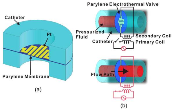
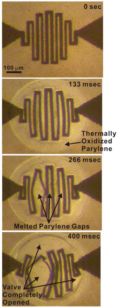
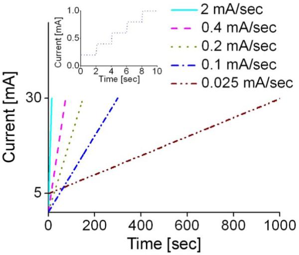
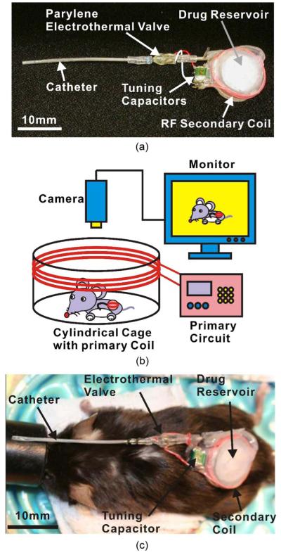
The first microelectromechanical-system normally closed electrothermal valve constructed using Parylene C is described, which enables both low power (in milliwatts) and rapid operation (in milliseconds). This low-power valve is well suited for applications in wirelessly controlled implantable drug-delivery systems. The simple design was analyzed using both theory and modeling and then characterized in benchtop experiments. Operation in air (constant current) and water (current ramping) was demonstrated. Valve-opening powers of 22 mW in air and 33 mW in water were obtained. Following integration of the valve with catheters, our valve was applied in a wirelessly operated microbolus infusion pump, and the in vivo functionality for the appropriateness of use of this pump for future brain mapping applications in small animals was demonstrated.


Figures

Fig. 1
Fig. 1
Parylene electrothermal valve. (a) Schematic diagram (cross-sectional view) illustrating the components of the valve. (b) Illustration of the operation principle of the valve in which wireless power transfer is used.
Fig. 2
Fig. 2
(a) Illustrations of the electrothermal valve layout in both top and cross-sectional views. (b) Photograph of a single valve. (c) Close-up of a valve element. Both (b) and (c) are reprints of Fig. 1(a) and (b) in [16], reprinted with the permission of the Chemical and Biological Microsystems Society.
Fig. 3
Fig. 3
Finite-element analysis using COSMOSWorks. (a) Nonlinear and transient FEM model and its corresponding coordinate system. (b) Stress distribution (1 atm).
Fig. 4
Fig. 4
(a) Schematic showing a 1-D heat-transfer model of the Parylene electrothermal valve. (b) and (c) Final model representing only the top half of the valve due to symmetry.
Fig. 5
Fig. 5
Finite-element analysis using COSMOSWorks: The results of transient thermal FEM modeling showing the temperature distribution of the valve at three time steps. This figure is a reprint of Fig. 2(d) in [16], reprinted with the permission of the Chemical and Biological Microsystems Society.
Fig. 6
Fig. 6
Fabrication process flow for the Parylene MEMS electrothermal valve. (a) Deposition of the bottom 5-μm-thick Parylene. (b) Liftoff lithography and Pt e-beam evaporation. (c) Pt liftoff. (d) Deposition of the top 5-μm-thick Parylene. (e) Contact-pad lithography and reactive ion etching. (f) Removal of photoresist, Parylene-film release, and hand dice of the device. This figure is a reprint of Fig. 5 in [1], reprinted with the permission of the Transducer Research Foundation.
Fig. 7
Fig. 7
Illustrated assembly process for the Parylene electrothermal valve. (a) Exploded view of components. (b) Conductive epoxy joins wires to the valve. (c) Epoxy bonding of the assembly. Photographs of (d) components for (left) the valve package and (right) the completely packaged valve in a catheter. Images (a)–(c) are reprints of Fig. 6(a)–(c) in [1], reprinted with the permission of the Transducer Research Foundation.
Fig. 8
Fig. 8
Schematic diagrams of the experimental apparatus for (a) load-deflection testing and (b) electromechanical testing that allow for visual observation of the electrothermal valve.
Fig. 9
Fig. 9
Comparison of the experimental data with the nonlinear FEM model and large-deflection approximation. This figure is a reprint in Fig. 4[1] reprinted with the permission of the Transducer Research Foundation.
Fig. 10
Fig. 10
Representative TCR calibration curve for an electrothermal valve. The slope of the curve corresponds to the empirically obtained TCR (α).
Fig. 11
Fig. 11
Representative OHT calibration curve showing (open square) the resistance and (open circle) OHT as a function of the applied current.
Fig. 12
Fig. 12
Results for valve opening in air. (a) Open valve (15 mA). (b) Magnified view of the edge of the valve orifice. (c) Valve-opening-current- and power-to-resistance relationship. This figure is a reprint of Fig. 8 in [1], reprinted with the permission of the Transducer Research Foundation.
Fig. 13
Fig. 13
Experimentally obtained time-sequence microscope images for valve-opening testing depicting the corresponding thermal events.
Fig. 14
Fig. 14
Current-ramping profile. The inset shows a close-up of the 0.1-mA/s waveform. For 0.025 mA/s, the opening time was shorted by initiating the applied current from 5 mA. This figure is a reprint of Fig. 10 in [1], reprinted with the permission of the Transducer Research Foundation.
Fig. 15
Fig. 15
Representative results for valve opening in water. (Left column) Real-time resistance monitoring of the valve. (Right column) Time-lapse images of valve opening corresponding to resistance-measurement events in the left column plots. (a)–(c) Valve-opening testing results corresponding to three valve designs A, B, and C, respectively. Fig. 15(a) is a reprint of Fig. 9 in [1], reprinted with the permission of the Transducer Research Foundation.
Fig. 16
Fig. 16
Neuroimaging application of Parylene electrothermal valve. (a) MIP. (b) In vivo testing setup. (c) Photograph comparing the MIP and a mouse. Fig. 16(a) and (c) are reprints of Fig. 11(a) and (b) in [1], reprinted with the permission of the Transducer Research Foundation.

References

    1. Li P-Y, Givrad TK, Holschneider DP, Maarek J-MI, Meng E. A wirelessly-activated Parylene electrothermal valve for mapping brain function in freely moving subjects; presented at the Solid-State Sensors, Actuators, Microsystems Workshop; Hilton Head Island, SC. 2008.
    1. Meng E, Li P-Y, Tai Y-C. A biocompatible Parylene thermal flow sensing array. Sens. Actuators A, Phys. 2008 May;144(1):18–28.
    1. Li P-Y, Shih J, Lo R, Saati S, Agrawal R, Humayun MS, Tai Y-C, Meng E. An electrochemical intraocular drug delivery device. Sens. Actuators A, Phys. 2008 May;143(1):41–48.
    1. Maloney JM, Uhland SA, Polito BF, Sheppard NF, Jr., Pelta CM, Santini JT., Jr. Electrothermally activated microchips for implantable drug delivery and biosensing. J. Control. Release. 2005 Dec.109(1–3):244–255. - PubMed
    1. Cardenas-Valencia AM, Dlutowski J, Bumgarner J, Munoz C, Wang W, Popuri R, Langebrake L. Development of various designs of low-power MEMS valves for fluidic applications. Sens. Actuators A, Phys. 2007 May;136(1):374–384.

LinkOut - more resources