

Automatic design of digital synthetic gene circuits
- PMID: 21399700
- PMCID: PMC3048778
- DOI: 10.1371/journal.pcbi.1001083
Automatic design of digital synthetic gene circuits
Abstract
De novo computational design of synthetic gene circuits that achieve well-defined target functions is a hard task. Existing, brute-force approaches run optimization algorithms on the structure and on the kinetic parameter values of the network. However, more direct rational methods for automatic circuit design are lacking. Focusing on digital synthetic gene circuits, we developed a methodology and a corresponding tool for in silico automatic design. For a given truth table that specifies a circuit's input-output relations, our algorithm generates and ranks several possible circuit schemes without the need for any optimization. Logic behavior is reproduced by the action of regulatory factors and chemicals on the promoters and on the ribosome binding sites of biological Boolean gates. Simulations of circuits with up to four inputs show a faithful and unequivocal truth table representation, even under parametric perturbations and stochastic noise. A comparison with already implemented circuits, in addition, reveals the potential for simpler designs with the same function. Therefore, we expect the method to help both in devising new circuits and in simplifying existing solutions.
Conflict of interest statement
The authors have declared that no competing interests exist.
Figures
 ,
,  and
and  ) are taken into account. The values of
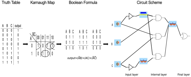
  are written on the rows of the Karnaugh map, whereas the values of
  and
and  lie on its columns. The Karnaugh map method permits to derive both the SOP and POS form of the Boolean expression associated with any truth table. Here, only the SOP calculation is shown (see Text S1 for a more detailed explanation of the method). The circuit scheme follows straightforwardly: each variable that is negated in one or more clauses (
 and
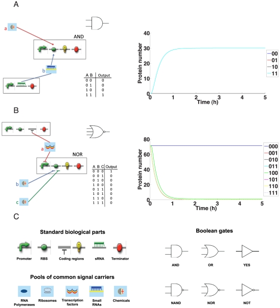
and  in the example) demands a NOT gate in the input layer. Every clause corresponds to an AND gate of the internal layer. An OR gate in the final layer gathers and sums the binary outputs of the internal AND gates. In the example, chemicals, sRNAs and transcription factors regulate the three AND gates that produce a unique kind of activator able to control the final OR gate.
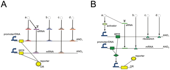
 is here represented both (A) as the circuit provided by Rinaudo et al.
with
is here represented both (A) as the circuit provided by Rinaudo et al.
with  different siRNAs and (B) as one of the
  solutions computed by our tool, using two activators and one sRNA. Notice that
  and
and  correspond to
  and
and  , respectively. Dashed lines indicate either protein synthesis or input signal conversion into a regulatory factor (NOT operation). For a better comparison with Rinaudo's scheme, we do not include the input layer in (B).
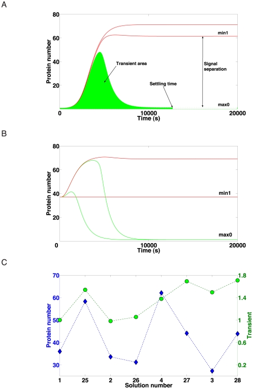
 outputs lie between the two red lines,
  outputs on the green surface). (B) Test case A solution
  simulation. Only the results of four (out of sixteen) truth table entries are shown. All the
  outputs lie between the red lines and all the
  outputs between the green ones. Every simulation consisted of two steps. First, the system reached a first steady state in the absence of chemicals (not shown). Afterwards, input signals were sent to the circuit. As a response, the network varied the reporter protein production and settled to a new steady state that describes the output (
 or
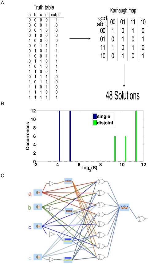
or  ) of the corresponding entry in the truth table. (C) Signal separation and transient for eight different solution of test case A. Transients have been rescaled with respect to the solution 1 value.
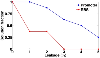
 ) for different promoter and RBS leakage rates. Leakage rate is expressed as a percentage of the fixed transcription/translation rate of the gates that belongs to the circuit internal gates.
References
-
- Endy D. Foundations for engineering biology. Nature. 2005;438:449–453. - PubMed
-
- Marchisio MA, Stelling J. Computational design tools for synthetic biology. Curr Opin Biotechnol. 2009;20:479–485. - PubMed
-
- Goler JA. BioJADE: A Design and Simulation Tool for Synthetic Biological Systems. 2004. Technical report, MIT, Cambridge, MA.
-
- Marchisio MA, Stelling J. Computational design of synthetic gene circuits with composable parts. Bioinformatics. 2008;24:1903–1910. - PubMed
Publication types
MeSH terms
Substances
LinkOut - more resources
Full Text Sources
