. 2011 Jul;39(7):2046-58.
doi: 10.1007/s10439-011-0291-8. Epub 2011 Mar 15.

Flow visualization of a pediatric ventricular assist device during stroke volume reductions related to weaning

Affiliations

Flow visualization of a pediatric ventricular assist device during stroke volume reductions related to weaning

Breigh N Roszelle et al. Ann Biomed Eng. 2011 Jul.

Abstract

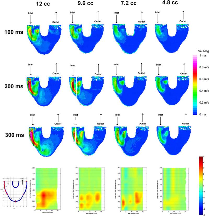
The aim of this study is to define the fluid mechanics of a pulsatile pneumatically driven pediatric ventricular assist device (PVAD), for the reduced flow rates encountered during device weaning and myocardial recovery, and relate the results to the potential for thromboembolic events. We place an acrylic model of the PVAD in a mock circulatory loop filled with a viscoelastic blood analog and operate at four stroke volumes (SVs), each with two different filling conditions, to mimic how the flow rate of the device may be reduced. Particle image velocimetry is used to acquire flow field data. We find that a SV reduction method provides better rotational flow and higher wall shear rates than a beat rate reduction method; that a quick filling condition with a compressed diastolic time is better than a slow filling condition; and, that a reduction in SV to 40% led to greatly reduced fluid movement and wall shear rates that could increase the thrombogenicity of the device. SV reduction is a viable option for flow reduction during weaning, however, it does lead to significant changes to the device flow field and future studies are needed to develop operational protocols for the PVAD during bridge-to-recovery.


Figures

FIGURE 1
FIGURE 1
Waveforms representative of the (a) quick and (b) slow filling conditions at a 12 cc SV. The drive pressure (green) is the pressure waveform from the airline of the pneumatic driver used to run the pump. The inlet pressure (orange) is representative of the atrial pressure and is obtained from the compliance chamber upstream of the PVAD. The outlet pressure (purple) is representative of the aortic pressure and is obtained from the compliance chamber downstream of the PVAD. The inflow waveform is measured just upstream of the PVAD inlet valve and the outflow waveform just downstream of the outlet valve.
FIGURE 2
FIGURE 2
An (a) artist's rendition of the PVAD implanted clinically, (b) a drawing of the pulsatile PVAD used, and the (c, d) PIV planes used labeled on the acrylic model. All of the distances are in mm. (c) shows the 7, 8.2 and 11 mm planes parallel to the diaphragm of the device. (d) shows the 7 planes taken normal to the diaphragm. Three planes each were taken in the outlet and inlet ports, and one plane was taken directly in the center of the device.
FIGURE 3
FIGURE 3
The 7 mm parallel plane of the (left to right) 12, 9.6, 7.2, and 4.8 cc quick filling conditions at (top row) 100 ms and (middle row) 150 ms. A strong inlet jet is observed during early diastole (100 ms) for all four SVs. The start of the rotational flow field is observed 50 ms later. The 4.8 cc SV contains reduced inlet jet velocities compared to the larger SVs. Also Surface 1 of the 7 mm parallel plane (bottom row), located along the outside inlet wall and highlighted in red to the bottom left of all four SVs. The wall shear rate maps have been normalized by the 500 s–1 design metric. Shear in the clockwise direction is positive, and the counterclockwise direction is negative; therefore low shear is indicated by the green color between 1 and –1 on the color legend. All four SVs contain high wall shear rates. However, the three larger SVs maintain these along the entire surface. The 12 cc SV contains these higher rates for the longest duration.
FIGURE 4
FIGURE 4
The 8.2 mm parallel plane of the (left to right) 12, 9.6, 7.2, and 4.8 cc quick filling conditions at (top row) 150 and (bottom row) 200 ms. As the flow progresses to mid diastole the inlet jets begin to dissipate, the lower SVs showing the largest drops in velocity magnitude.
FIGURE 5
FIGURE 5
The 3.75 mm normal inlet plane of the (left to right) 12, 9.6, 7.2, and 4.8 cc quick filling conditions at (top row) 50, (middle row) 150, and (bottom row) 250 ms. The inlet jet formation in the outermost normal inlet plane shows the early onset of the jet, and the early dissipation as the SV is reduced.
FIGURE 6
FIGURE 6
Surface 4 of the 3.75 mm normal inlet plane, located in the middle of the fluid side of the inlet as highlighted in red to the right, of the (a) 12, (b) 9.6, (c), 7.2, and (d) 4.8 cc quick filling conditions. Similarly to the wall shear rate maps of the 7 mm parallel plane seen in Fig. 3, high wall shear rates (>1000 s–1) are observed early in diastole for all SVs except 4.8 cc. The 12 cc SV also still contains the highest wall shear rates for the longest duration.
FIGURE 7
FIGURE 7
A plot of the maximum velocities versus time of all four quick fill SVs in the 8.2 mm parallel plane. A loss of velocity strength can be seen with each SV.
FIGURE 8
FIGURE 8
The 11 mm parallel plane of the (left to right) 12, 9.6, 7.2, and 4.8 cc quick filling conditions at (top row) 200, (middle row) 300, and (bottom row) 400 ms. All three larger SVs show a strong rotational flow field at mid diastole (200 ms), however, the 9.6 and 7.2 cc SVs show more dissipation of this rotation before the end of diastole than the 12 cc SV. The 4.8 cc stroke volume never fully develops a rotational flow field.
FIGURE 9
FIGURE 9
Surface 3 of the 11 mm parallel plane, located at the bottom wall of the outlet side as highlighted in red to the right, of the (a) 12, (b) 9.6, (c) 7.2, and (d) 4.8 cc quick filling conditions. As shown previously on the inlet walls the 12 cc SV maintains higher wall shear rates for the longest duration. The lower SVs then show a drop in both wall shear rate magnitude and duration, with very low wall shear seen at the 7.2 and 4.8 cc SVs (c, d).
FIGURE 10
FIGURE 10
The 7 mm parallel plane of the (left to right) 12, 9.6, 7.2, and 4.8 cc slow filling conditions at (top row) 100, (top middle row) 200, and (bottom middle row) 300 ms. The inlet jet can be seen developing throughout diastole. The 12 and 9.6 cc SVs show a rotational flow beginning after mid diastole. Also, surface 1 of the 7 mm parallel plane (bottom row), located along the outside inlet wall and highlighted in red to the left, for all four SVs. The 12 cc SV conditions contains wall shear rates above the 500 s–1 threshold for a large portion of diastole, however, the smaller SVs show less uniform washing of the inlet surface.
FIGURE 11
FIGURE 11
The 11 mm parallel plane of the (left to right) 12, 9.6, 7.2, and 4.8 cc slow filling conditions at (top row) 200, (middle row) 300, and (bottom row) 400 ms. A weak rotational flow field has developed in the 12 and 9.6 cc SVs at the end of diastole (400 ms). A rotational flow field is never fully developed in either the 7.2 or 4.8 cc SVs.
FIGURE 12
FIGURE 12
Surface 3 of the 11 mm parallel plane, located at the bottom wall of the outlet side as highlighted in red to the right, of the (a) 12, (b) 9.6, (c) 7.2, and (d) 4.8 cc slow filling conditions. The (a) 12 cc SV is the only condition with wall shear rates above the desired 500 s–1 threshold. The other three SVs show almost no change in the wall shear rates across the entire cycle for this surface.

Similar articles

Cited by

References

    1. Almond C, Thiagarajan R, Piercey G, Gauvreau K, Blume E, Bastardi H, Fynn-Thompson F, Singh T. Waiting list mortality among children listed for heart transplantation in the United States. Circulation. 2009;119:717–727. - PMC - PubMed
    1. Arabia FA, Tsau PH, Smith RG, et al. Pediatric bridge to heart transplantation: application of the berlin heart, medos and thoractec ventricular assist devices. J. Heart Lung Transplant. 2006;25:16–21. - PubMed
    1. Baldwin JT, Deutsch S, Geselowitz DB, Tarbell JM. LDA measurements of mean velocity and reynolds stress fields within an artificial heart ventricle. J. Biomech. Eng. 1994;116:190–200. - PubMed
    1. Carney EL, Clark JB, Myers JL, Peterson R, Wilson RP, Weiss WJ. Animal model development for the Penn State pediatric ventricular assist device. Artif. Organs. 2009;33(11):853–957. - PMC - PubMed
    1. Cavanaugh JL, Miyamoto SD, da Cruz E, et al. Predicting recovery: successful explant of a ventricular assist device in a child with dilated cardiomyopathy. J. Heart Lung Transplant. 2010;29:105–108. - PubMed

Publication types