

Review
doi: 10.1148/radiol.11100155.
Focused ultrasound surgery in oncology: overview and principles
Affiliations
- PMID: 21436096
- PMCID: PMC3064817
- DOI: 10.1148/radiol.11100155
Item in Clipboard
Review
Focused ultrasound surgery in oncology: overview and principles
Radiology.
2011 Apr.
Abstract
Focused ultrasound surgery (FUS) is a noninvasive image-guided therapy and an alternative to surgical interventions. It presents an opportunity to revolutionize cancer therapy and to affect or change drug delivery of therapeutic agents in new focally targeted ways. In this article the background, principles, technical devices, and clinical cancer applications of image-guided FUS are reviewed.
© RSNA, 2011.
Figures
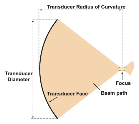
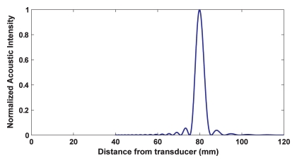
(a) Diagram shows properties of a geometrically focused transducer. (b) Normalized acoustic intensity along the direction of ultrasound propagation for a 1.5-MHz transducer with a radius of curvature of 8 cm and diameter of 10 cm.
(a) Diagram shows properties of a geometrically focused transducer. (b) Normalized acoustic intensity along the direction of ultrasound propagation for a 1.5-MHz transducer with a radius of curvature of 8 cm and diameter of 10 cm.
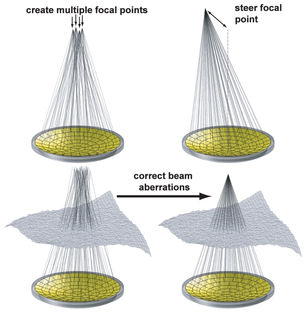
Ways a phased-array transducer can be used include producing multiple focal spots to increase the ablated volume per sonication, steering the focal point to different locations, and correcting for aberrations caused by tissue structures in the ultrasound beam path.
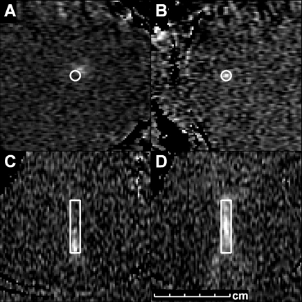
Temperature images acquired during sonications to ensure correct targeting of the focal coordinate. A and C were acquired before the focal coordinate was corrected; B and D were acquired after correction. A, B, First, sonications were performed with temperature imaging perpendicular to the ultrasound beam direction. C, D, Next, sonications were performed with imaging along the beam direction. (Reprinted, with permission, from reference .)

Contrast-enhanced T1-weighted images (subtraction image) of a localized breast cancer mass (left) before and (right) after MR-guided FUS. The size of the region of nonperfusion (green outline) is larger than the original mass and includes a surgical margin. An adjacent area of contrast enhancement (arrow) may be difficult to distinguish from residual tumor, and thus would require further treatment before ending the procedure.
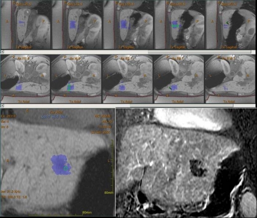
MR-guided FUS of hepatocellular carcinoma. Series in sagittal and axial planes show a small focal area of treatment; green regions = location of current sonication, blue areas = those that have been treated to the desired temperature in left lobe of the liver. Bottom left: Final posttreatment image in coronal plane shows entire thermal dose history. Bottom right: Image after intravenous gadolinium administration shows the focal nonperfusion. (Image courtesy of Wadyslaw Gedroyc, MD, St Mary’s Hospital, London, England.)
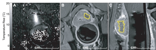
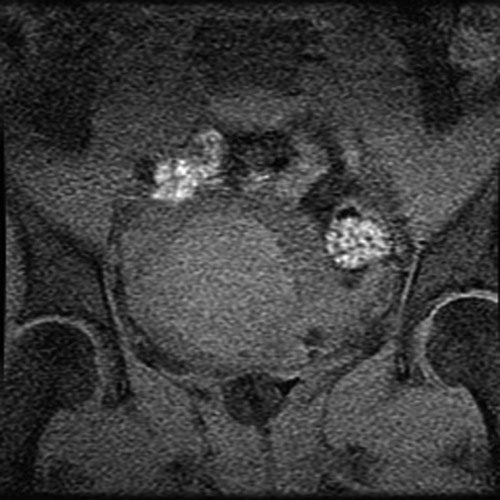
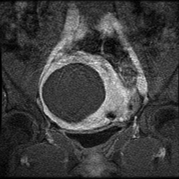
Preclinical MR-guided FUS of the prostate. Three images from an animal study show, A, axial phase image with thermal change (high-signal-intensity area centrally) from an individual sonication delivered by transrectal FUS transducer device (Insightec), then, B, axial T1-weighted and, C, sagittal T1-weighted images after the procedure and after injection of intravenous gadolinium show the focal ablation as an area of nonperfusion (yellow).
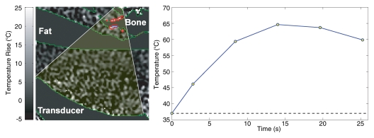
MR-guided FUS of bone tumors. (a) Schematic of bone treatment. FUS beam is oriented so its axis of propagation is normal to the bone surface. The focal point is placed behind the bone surface. Because absorption in bone is so much greater than in soft tissue, a large area can be heated in a single sonication. (b) Axial T2-weighted image in patient undergoing MR-guided FUS for large bone metastasis in right acetabulum. The transducer is directly posterior to the pelvis on the right. (c) Axial-oblique echo-planar imaging temperature map during MR-guided FUS. The bone surface is heated, raising the temperature in the adjacent tumor above the ablation area. Temperature drops off rapidly away from the bone. Red contours = regions that reached a thermal dose of at least 240 equivalent min at 43°C. The bone in the beam path for this sonication was fairly thin, and both sides of the bone were heated.
MR-guided FUS of bone tumors. (a) Schematic of bone treatment. FUS beam is oriented so its axis of propagation is normal to the bone surface. The focal point is placed behind the bone surface. Because absorption in bone is so much greater than in soft tissue, a large area can be heated in a single sonication. (b) Axial T2-weighted image in patient undergoing MR-guided FUS for large bone metastasis in right acetabulum. The transducer is directly posterior to the pelvis on the right. (c) Axial-oblique echo-planar imaging temperature map during MR-guided FUS. The bone surface is heated, raising the temperature in the adjacent tumor above the ablation area. Temperature drops off rapidly away from the bone. Red contours = regions that reached a thermal dose of at least 240 equivalent min at 43°C. The bone in the beam path for this sonication was fairly thin, and both sides of the bone were heated.
MR-guided FUS of bone tumors. (a) Schematic of bone treatment. FUS beam is oriented so its axis of propagation is normal to the bone surface. The focal point is placed behind the bone surface. Because absorption in bone is so much greater than in soft tissue, a large area can be heated in a single sonication. (b) Axial T2-weighted image in patient undergoing MR-guided FUS for large bone metastasis in right acetabulum. The transducer is directly posterior to the pelvis on the right. (c) Axial-oblique echo-planar imaging temperature map during MR-guided FUS. The bone surface is heated, raising the temperature in the adjacent tumor above the ablation area. Temperature drops off rapidly away from the bone. Red contours = regions that reached a thermal dose of at least 240 equivalent min at 43°C. The bone in the beam path for this sonication was fairly thin, and both sides of the bone were heated.
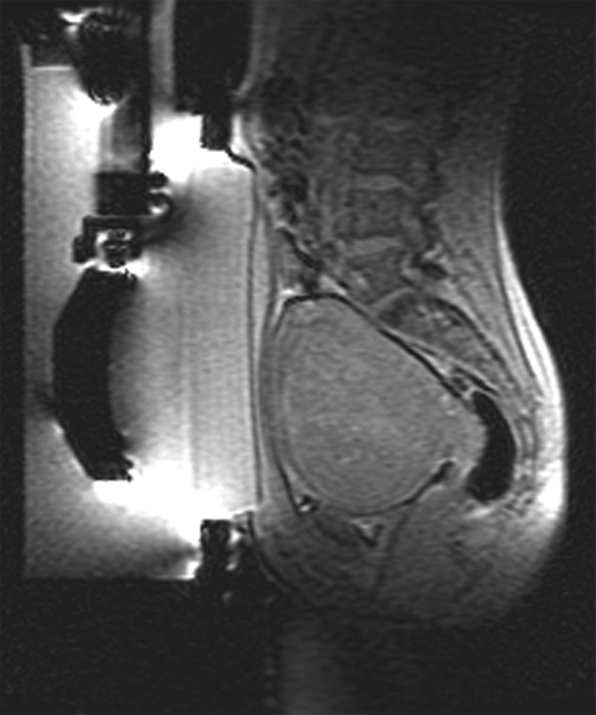
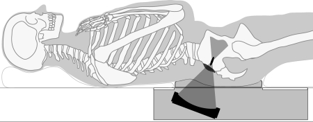
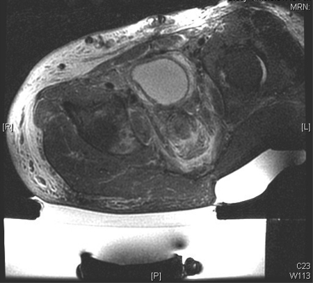
MR-guided FUS of uterine fibroid. (a) Sagittal image shows patient set up and the FUS transducer system on the left. Images (b) before and (c) after intravenous gadolinium administration, acquired immediately after treatment, demonstrate the focal nonperfused fibroid as a result of the ablation.
MR-guided FUS of uterine fibroid. (a) Sagittal image shows patient set up and the FUS transducer system on the left. Images (b) before and (c) after intravenous gadolinium administration, acquired immediately after treatment, demonstrate the focal nonperfused fibroid as a result of the ablation.
MR-guided FUS of uterine fibroid. (a) Sagittal image shows patient set up and the FUS transducer system on the left. Images (b) before and (c) after intravenous gadolinium administration, acquired immediately after treatment, demonstrate the focal nonperfused fibroid as a result of the ablation.
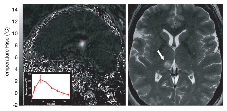
MR-guided FUS in the brain for functional neurosurgery. A right centrolateral thalamotomy was performed with transcranial MR-guided FUS in a 50-year-old female patient with chronic therapy-resistant neuropathic pain in the left trigeminal nerves V2 and V3. Two locations were sonicated to create a lesion of suitable size to cover the target area. Left: MR temperature map at peak heating (inset = temperature/time curve in 3 × 3 voxel region at the focal point). Right: Axial T2-weighted image shows the resulting lesion (arrow). (Images courtesy of University Children’s Hospital, Zurich, Switzerland.)
References
-
- Wood RW, Loomis AL. The physical and biological effects of high frequency sound waves of great intensity. Philos Mag Ser 7 1927;4(22):417–436
-
- Seabrook W. Doctor Wood, modern wizard of the laboratory: the story of an American small boy who became the most daring and original experimental physicist of our day—but never grew up. New York, NY: Harcourt, Brace, 1941
-
- Moonen CT. Spatio-temporal control of gene expression and cancer treatment using magnetic resonance imaging-guided focused ultrasound. Clin Cancer Res 2007;13(12):3482–3489 - PubMed
-
- McDannold NJ, Jolesz FA. Magnetic resonance image-guided thermal ablations. Top Magn Reson Imaging 2000;11(3):191–202 - PubMed
-
- Lindner JR, Jr, Song J, Christiansen J, Klibanov AL, Xu F, Ley K. Ultrasound assessment of inflammation and renal tissue injury with microbubbles targeted to P-selectin. Circulation 2001;104(17):2107–2112 - PubMed
Publication types
MeSH terms
Grants and funding
LinkOut - more resources
Full Text Sources
Other Literature Sources
