. 2011 May 7;11(9):1688-93.
doi: 10.1039/c1lc20089e. Epub 2011 Mar 28.

A membrane-based, high-efficiency, microfluidic debubbler

Affiliations

A membrane-based, high-efficiency, microfluidic debubbler

Changchun Liu et al. Lab Chip. .

Abstract

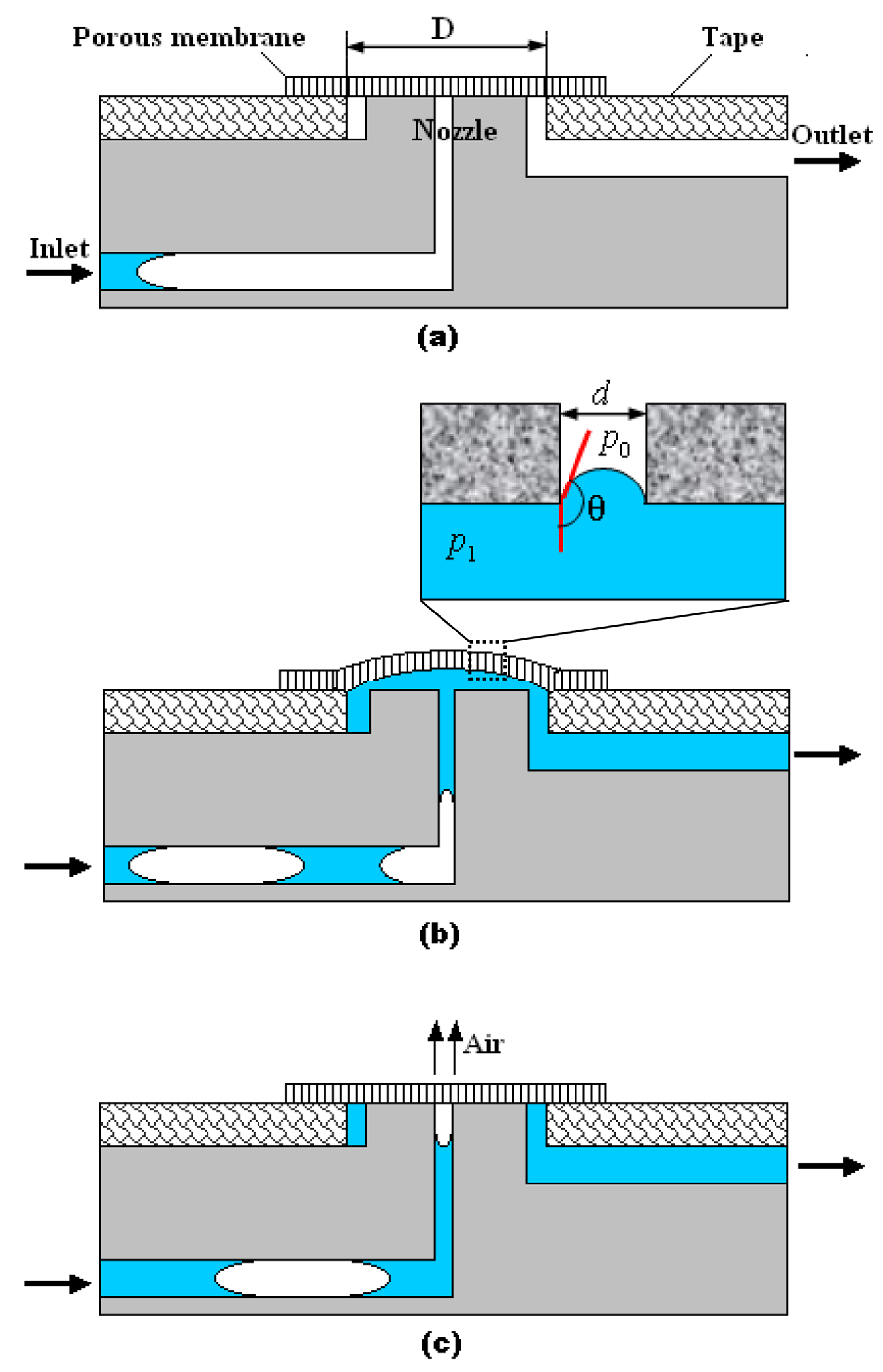
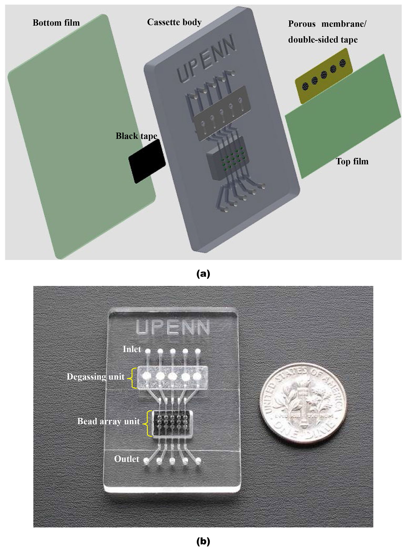
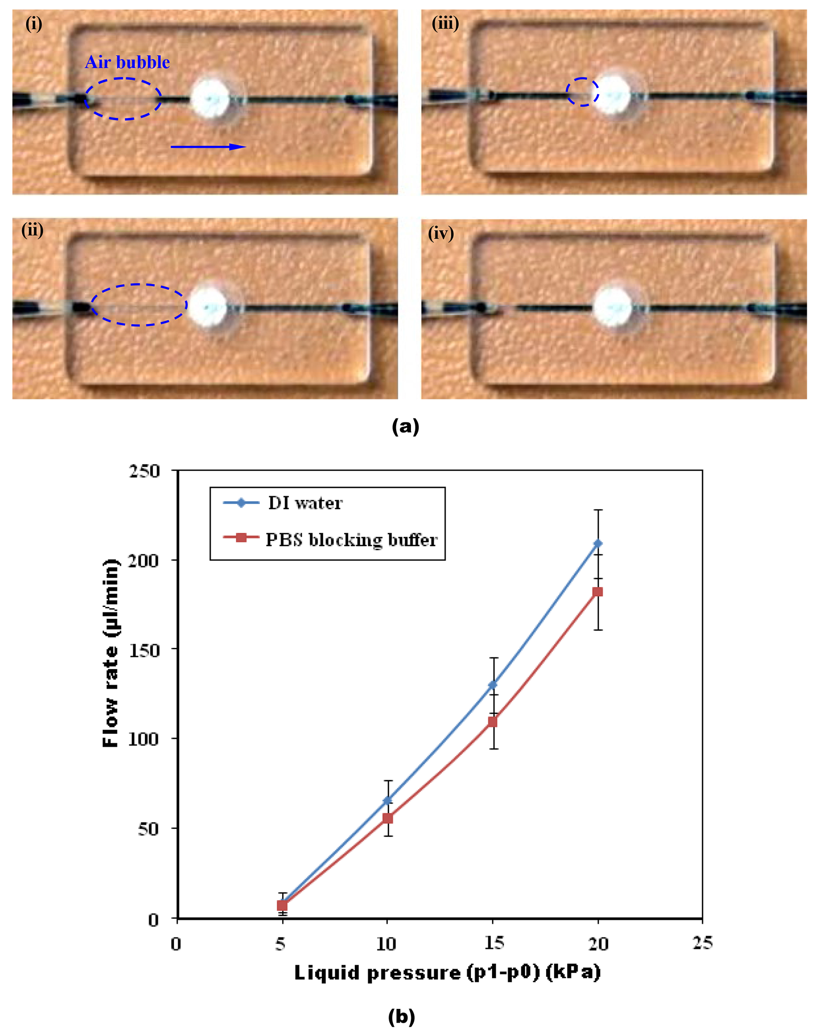
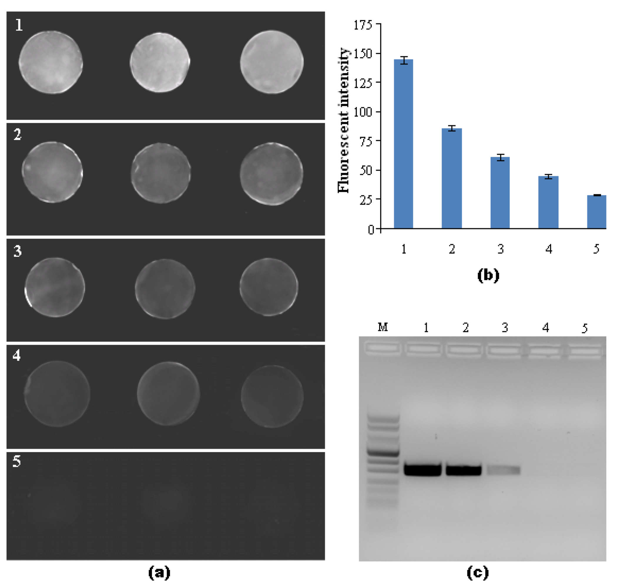
In many lab-on-chip applications, it is necessary to remove bubbles from the flow stream. Existing bubble removal strategies have various drawbacks such as low degassing efficiency, long degassing time, large dead volumes, sensitivity to surfactants, and the need for an external vacuum or pressure source. We report on a novel, simple, robust, passive, nozzle-type, membrane-based debubbler that can be readily incorporated into microfluidic devices for rapid degassing. The debubbler is particularly suitable to operate with microfluidic systems made with plastic. The debubbler consists of a hydrophobic, porous membrane that resembles a normally closed valve, which is forced open by the working fluid's pressure. To illustrate the operation of the debubbler, we describe its use in the context of a chip containing a bead array for immunoassays. Our debubbler was able to completely filter gas bubbles out of a segmented flow at rates up to 60 µl s(-1) mm(-2) of membrane area.


Figures

Fig. 1:
Fig. 1:
A schematic depiction of the debubbler and its degassing principle: (a) Initial, closed state before liquid has entered the debubbler. (b) Open state with liquid in the debubbler. The inset shows an air–liquid meniscus which is pinned at the pore’s entrance; surface tension maintains the pressure difference across the meniscus and prevents liquid from leaking through the pore. (c) Closed state with air bubble in the debubbler. The bubble was forced to discharge through the hydrophobic pore of the PTFE membrane.
Fig. 2:
Fig. 2:
Bead array-based microfluidic cassette with integrated debubbler. (a) Exploded view of integrated cassette. The cassette consists of a top PMMA film, porous membranes within double-sided tape, a PMMA cassette body, agarose beads, black tape, and a bottom PMMA film. All microstructure features including nozzles, microchannels, and the 5 × 3 well array are milled in the PMMA cassette’s body. (b) A photograph of the assembled cassette.
Fig. 3:
Fig. 3:
(a) A sequence of images illustrating the bubble removal process from DI water in the membrane-based debubbler. Bubbles traveling from left to right at a flow rate of 200 μl/min are completely removed from the liquid stream through the porous membrane. (i) 0 s. A bubble enters the debubbler. (ii) 0.1 s. The bubble enters the membrane region. (iii) 0.2 s. The bubble is vented. (iv) 0.3 s. The liquid downstream of the membrane is completely free of bubbles. (b) The flow rates of DI water and PBS blocking buffer through the debubbler as functions of liquid pressure (p1p0) at the debubbler’s inlet. The error bars correspond to the scatter of the data obtained in three experiments.
Fig. 4:
Fig. 4:
Detection of PCR amplicons of B. Cereus genomic DNA: (a) A fluorescent image of three streptavidin-coated beads at different DNA concentrations in the integrated microfluidic debubbler cassette. Groups 1, 2, 3, 4 and 5 correspond, respectively, to template masses of 10, 1, 0.1, 0.01 and 0 ng (negative control) of DNA. (b) Measured intensity of agarose beads at different PCR amplicon concentrations obtained from 0 to 10 ng template. The various samples are cross-referenced with (a). The error bars correspond to the scatter of the data obtained in six agarose beads. (c) Agarose gel (2.0%) electrophoresis images of PCR products amplified from B. Cereus genomic DNA. The various lanes are cross-referenced with (a). Lane M is the DNA Marker VIII ladder.

Similar articles

Cited by

References

    1. Meng DD, Cubaud T, Ho C-M and Kim C-J, J. Microelectromech. Syst, 2007, 16, 1403–1410.
    1. Leclerc E, Sakai Y and Fujii T, Biomed. Microdevices, 2003, 5, 109–114.
    1. Kim L, Vahey MD, Lee H-Y and Voldman J, Lab Chip, 2006, 6, 394–406. - PubMed
    1. Nakayama T, Hiep HM, Furui S, Yonezawa Y, Saito M, Takamura Y, Tamiya E, Anal. Bioanal. Chem, 2010, 396, 457–464. - PubMed
    1. Sohn YS, Goodey A, Anslyn EV, McDevitt JT, Shear JB, Neikirk DP, Biosens Bioelectron., 2005, 21, 303–312. - PubMed

Publication types

LinkOut - more resources