. 2011 Apr 1;145(1):54-66.
doi: 10.1016/j.cell.2011.02.038.

The Mre11:Rad50 structure shows an ATP-dependent molecular clamp in DNA double-strand break repair

Affiliations

The Mre11:Rad50 structure shows an ATP-dependent molecular clamp in DNA double-strand break repair

Katja Lammens et al. Cell. .

Abstract

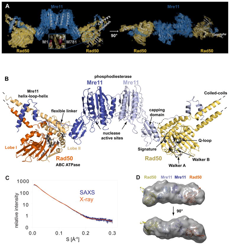
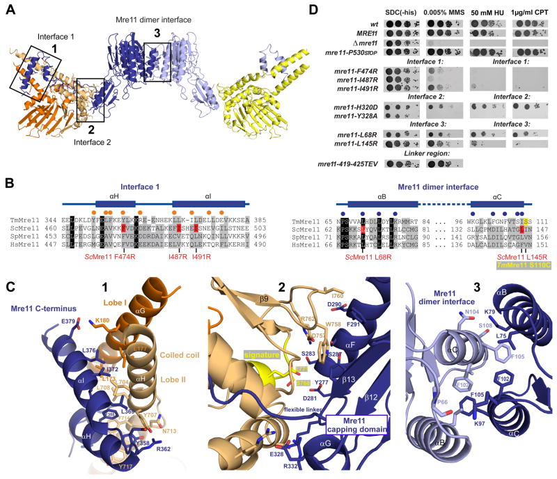
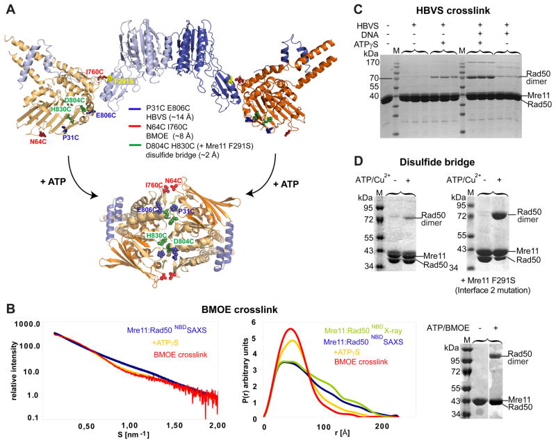
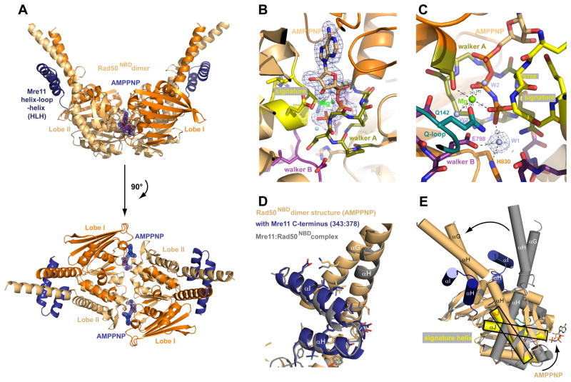
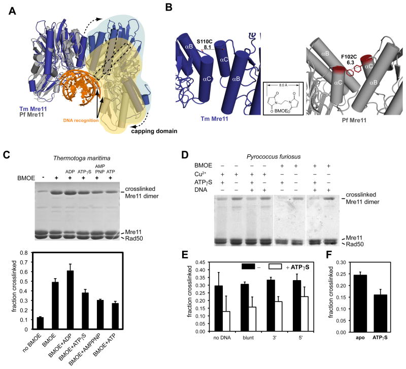
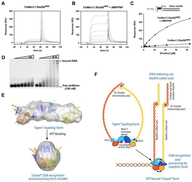
The MR (Mre11 nuclease and Rad50 ABC ATPase) complex is an evolutionarily conserved sensor for DNA double-strand breaks, highly genotoxic lesions linked to cancer development. MR can recognize and process DNA ends even if they are blocked and misfolded. To reveal its mechanism, we determined the crystal structure of the catalytic head of Thermotoga maritima MR and analyzed ATP-dependent conformational changes. MR adopts an open form with a central Mre11 nuclease dimer and two peripheral Rad50 molecules, a form suited for sensing obstructed breaks. The Mre11 C-terminal helix-loop-helix domain binds Rad50 and attaches flexibly to the nuclease domain, enabling large conformational changes. ATP binding to the two Rad50 subunits induces a rotation of the Mre11 helix-loop-helix and Rad50 coiled-coil domains, creating a clamp conformation with increased DNA-binding activity. The results suggest that MR is an ATP-controlled transient molecular clamp at DNA double-strand breaks.


Figures

Figure 1
Figure 1. Overall structure of the crescent-shaped Mre11:Rad50 catalytic head
A) Experimental electron density map (contoured at 1.0 σ and colored blue for Mre11 and yellow for Rad50) superimposed with a ribbon representation of the Thermotoga maritima Mre11:Rad50NBD complex (gray). Two views are shown. Inset: anomalous difference electron density map for the selenium atoms (pink, contoured at 5.0 σ). B) Ribbon representation of the bacterial Rad50 Mre11 catalytic head. Individual domains and important motifs are highlighted and annotated. C) Experimental small angle X-ray scattering (SAXS) profile of Mre11:Rad50NBD (blue) compared to the theoretical scattering curve calculated from the crystal structure of the complex (orange). D) Two orthogonal views of the average SAXS envelope of the Mre11:Rad50NBD assemblies (calculated with DAMMIN, superimposed with a ribbon representation of the atomic model of the complex) highlight the similarity of crystals structure and solution conformation. See also Figure S1 and Table S1.
Figure 2
Figure 2. Details of Mre11:Rad50NBD and the Mre11 dimer interfaces
A) Ribbon representation of the Mre11:Rad50NBD complex colored according to figure 1B. The boxed interfaces (1,2,3) are shown in C). B) Sequence alignment of the Mre11 HLH domain (αH and αI) and the Mre11 dimer interface (αB and αC). Yeast mutations analyzed in D) are highlighted in red. Spheres represent residues implicated in Mre11HLH:Rad50NBD (orange) and Mre11:Mre11 interaction (blue). C) Details of macromolecular interfaces. Selected side chains are shown as color-coded sticks and are annotated. 1) The Mre11 helix-loop-helix (HLH) motif (blue) and its interaction with the base of the Rad50 coiled coil (orange and yellow). 2) The interface between the capping domain of Mre11 (blue) and the opposite Rad50 (orange) region in close proximity to the signature motif (yellow). 3) The Mre11 dimerization interface. D) Yeast survival assays by serial dilutions show that mutations in Mre11 predicted to affect interface 3 (L145R, L68R), mutations within the helix-loop-helix motif predicted to affect interface 1 (L474R, I487R, I491R), and mutations in the capping domain predicted to affect interface 2 (H320D, Y328A) result in sensitivity to Methyl-methanesulfonate (MMS), hydroxyurea (HU) and camptothecin (CPT). Changing the flexible linker residues (419–425 TEV) has no strong effect on MMS sensitivity. Left: SDC medium without histidine alone. Right: media supplemented with indicated concentrations of MMS, HU or CPT. See also Figure S2.
Figure 3
Figure 3. ATP engages Rad50NBDs in the catalytic head
A) Cysteine mutations introduced in TmRad50NBD to test formation of the ATP bound Rad50 dimer. Sites are widely separated in the open form (upper crystal structure), but closely spaced for crosslinking or disulfide bonding in the ATP bound form (below, see Fig. 4). B) Left panel: Superposition of experimental SAXS curves of Mre11:Rad50NBD with and without ATPγS indicate a more compact, globular shape in the presence of ATPγS. SAXS of the BMOE crosslinked Mre11:Rad50NBD,N64C,I760C results in a shape similar to the ATPγS bound form. Middle panel: the electron pair distance distribution function P(r) in the absence of nucleotides corresponds well to the crystal structure derived P(r). ATPγS increases the short distances and decreases the long distances. Residual long distances suggest a heterogeneous mixture between the open form and closed ATPγS complex. The BMOE crosslinked complex has a similar shape to the ATPγS complex, but appears to be more homogenous for the compact form. Right panel: Non-reducing Coomassie stained SDS PAGE of the MRNBD,N64C,I760C crosslinking experiment using BMOE. The crosslinking forms a covalently connected Rad50 dimer in an ATP dependent manner. C) Chemical crosslinking by HBVS of MRNBD,P31C,E806C creates a covalently connected Rad50 dimer in an ATPγS and DNA dependent manner. The identity of the corresponding gel band was confirmed by mass spectrometry. D) The formation of ATP bound engaged Rad50NBD,D804C,H830C is tested by using ATP/Cu2+ dependent disulfide bond formation. Modulating the Mre11:Rad50 interface 2 by Mre11F291S results in dramatically increased disulfide bond formation efficiency, consistent with the idea that interface 2 stabilizes the open form and is disrupted in the closed form. See also Figure S3.
Figure 4
Figure 4. Structure of the AMPPNP bound Rad50NBD dimer in complex with the HLH domain of Mre11
A) Two perpendicular views of a ribbon representation of the AMPPNP bound Rad50NBD dimer in complex with the C-terminal helix-loop-helix region of Mre11 color coded according to Fig. 1B. AMPPNP is highlighted and shown with 2FoFc electron density (1σ contour). B), C) Two views of the ATP binding site with 1.9 Å 2Fo−Fc electron density around AMPPNP (B) or the nucleophilic water (“W1” in C) and highlighted and color coded ATP binding motifs signature motif (yellow), Walker A (olive), Walker B (purple), Q-loop (turquoise) and Mg2+ ion (green sphere). D) Superposition of Rad50NBD from apo (from MR catalytic head, grey) and AMPPNP (blue/orange) crystal structures at Lobes II shows that for T. maritima MR, coiled-coil structure and interaction interface 1 is not directly modulated by AMPPNP binding. E) Superposition of apo and AMPPNP bound forms of Rad50NBDs via Lobe I shows that AMPPNP binding induces a large, approx. 50° rotation between Lobe I and Lobe II, leading to a rigid body movement (arrow) of the HLH and coiled coil with respect to the ATP binding interface of Rad50. See also Figure S4 and Table S2.
Figure 5
Figure 5. ATP binding to Rad50 changes the Mre11 dimer interface
A) Comparison of the nuclease dimer of DNA bound PfMre11 (grey, yellow, orange) with that of TmMre11 (blue, lightblue). Both complexes are superimposed via the left protomer. In T. maritima, the right protomer has to undergo a substantial rigid body motion to adopt the same DNA binding contacts (solid arrows) and conformation as seen for PfMre11 (dashed arrow). This can be seen by the different orientations of the minor groove binding helix (dashed rectangles). B) To probe for conformational changes, we mutated S110C in TmMre11 (left panel) and F102C in PfMre11 at a position that is expected to undergo movements when switching between different pivot angles. The distances are suitable for crosslinking with a short bifunctional sulfhydryl directed crosslinker (inset: BMOE), or by forming disulfide bonds. C) Crosslinking analysis of TmMre11 dimer structure. Upper panel, non-reducing Coomassie stained SDS PAGE of TmMRNBD crosslinked under different conditions (lane labels see lower panel); Lower panel, quantification of the crosslinking efficiency (mean +/− standard deviation of three independent experiments) for different conditions and adenosine nucleotides. A crosslinked band corresponding to the Mre11 dimer in the absence of BMOE crosslinker indicates disulfide bond formation. D) Coomassie stained non-reducing SDS PAGE of crosslinked PfMRNBD, showing different conditions and replicates. Cu2+ was used to increase disulfide bond formation. E) and F) Quantification of crosslinking efficiency by BMOE (E) or disulfide bonds (F). Error bars depict standard deviations. In F) the effect of ATPγS is tested. In E) the effect of dsDNA 50mer with either blunt ends or 3′ or 5′ 10 dT ssDNA overhangs is shown. Black bars are without ATPγS, white bars with ATPγS.
Figure 6
Figure 6. ATP stimulated dsDNA binding and clamp model for DSB sensing
A) and B) Surface Plasmon sensograms for binding of TmMre11:Rad50NBD to 50mer dsDNA in absence (A) and presence of AMPPNP (B). C) Corresponding binding curves reveals AMPPNP stimulated binding to dsDNA. AMPPNP also increases hairpin recognition (Fig. S6A) and we also observe increased binding affinity of the protein with crosslinked Rad50 NBDs (ATP mimic state) (data not shown). D) Electrophoretic mobility shift assays show that the MRNBD,H830C,D804C complex with a disulfide bond between the NBDs (S-S) has strongly increased dsDNA oligonucleotide binding affinity compared to the wildtype MRNBD complex (wt). Following concentrations of the protein (0, 1.0, 2.5, 5.0, 7.5, 10.0 and 15.0 μM respectively) were used. E) Model for the closed, clamp like complex with engaged NBDs by combining X-ray structures and SAXS analysis. “Open” (experimental) and “closed” (rigid body docked model) forms are displayed with corresponding SAXS envelopes. F) Proposed model for ATP dependent DSB sensing and processing by MR by formation of a transient clamp at DNA end structures. See also Figure S5.

References

    1. Bentchikou E, Servant P, Coste G, Sommer S. Additive effects of SbcCD and PolX deficiencies in the in vivo repair of DNA double-strand breaks in Deinococcus radiodurans. J Bacteriol. 2007;189:4784–4790. - PMC - PubMed
    1. Bhaskara V, Dupre A, Lengsfeld B, Hopkins BB, Chan A, Lee JH, Zhang X, Gautier J, Zakian V, Paull TT. Rad50 adenylate kinase activity regulates DNA tethering by Mre11/Rad50 complexes. Mol Cell. 2007;25:647–661. - PMC - PubMed
    1. Borde V. The multiple roles of the Mre11 complex for meiotic recombination. Chromosome Res. 2007;15:551–563. - PubMed
    1. Bowman GD, O’Donnell M, Kuriyan J. Structural analysis of a eukaryotic sliding DNA clamp-clamp loader complex. Nature. 2004;429:724–730. - PubMed
    1. Budd ME, Campbell JL. Interplay of Mre11 nuclease with Dna2 plus Sgs1 in Rad51-dependent recombinational repair. PLoS One. 2009;4:e4267. - PMC - PubMed

Publication types

MeSH terms