

Supernatant decanting on a centrifugal platform
- PMID: 21522503
- PMCID: PMC3082350
- DOI: 10.1063/1.3571477
Supernatant decanting on a centrifugal platform
Abstract
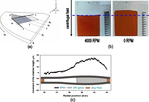
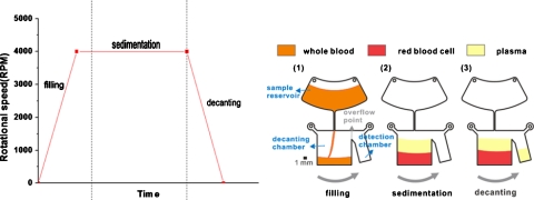
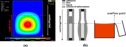
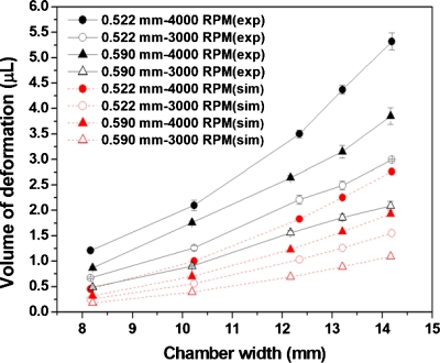
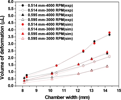
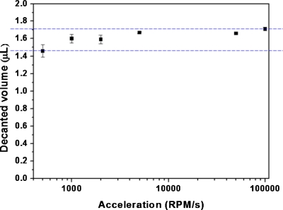
This study presents a novel approach to decant supernatant on a centrifugal platform. By manipulating the centrifugally induced pressure and the elastic deformation of the plastic lids in the decanting chamber, fixed amounts of the supernatant can be decanted into the detection chamber at lower rotational speeds. The experimental results showed that decanted volume is affected by the volume of deformation and the operating parameters. Factors that influence the decanting ratio are also discussed. This approach has the advantages of simple design and low manufacturing cost; further, it has no need of surface modification. It has been applied to on-disk separation of plasma from whole blood, and the results showed good stability and repeatability.
Figures
Similar articles
-
Extremely Precise Blood-Plasma Separation from Whole Blood on a Centrifugal Microfluidic Disk (Lab-on-a-Disk) Using Separator Gel.Diagnostics (Basel). 2022 Nov 20;12(11):2873. doi: 10.3390/diagnostics12112873. Diagnostics (Basel). 2022. PMID: 36428933 Free PMC article.
-
Network simulation-based optimization of centrifugo-pneumatic blood plasma separation.Biomicrofluidics. 2017 Apr 6;11(2):024114. doi: 10.1063/1.4979044. eCollection 2017 Mar. Biomicrofluidics. 2017. PMID: 28798850 Free PMC article.
-
Centrifugal extraction of plasma from whole blood on a rotating disk.Lab Chip. 2006 Jun;6(6):776-81. doi: 10.1039/b604145k. Epub 2006 Apr 13. Lab Chip. 2006. PMID: 16738730
-
Serum of Blood Separation by Means of Dynamic Electrochromatography in a Centrifugal and Electromagnetic Gradient.Recent Pat Biotechnol. 2014;8(3):215-30. doi: 10.2174/187220830803150605163521. Recent Pat Biotechnol. 2014. PMID: 27099145 Review.
-
Centrifugal microfluidics for biomedical applications.Lab Chip. 2010 Jul 21;10(14):1758-73. doi: 10.1039/b924109d. Epub 2010 May 28. Lab Chip. 2010. PMID: 20512178 Review.
Cited by
-
Euler force actuation mechanism for siphon valving in compact disk-like microfluidic chips.Biomicrofluidics. 2014 Mar 5;8(2):024101. doi: 10.1063/1.4867241. eCollection 2014 Mar. Biomicrofluidics. 2014. PMID: 24753736 Free PMC article.
-
Preface to Special Topic: Biological microfluidics in tissue engineering and regenerative medicine.Biomicrofluidics. 2011 Mar 30;5(1):13301. doi: 10.1063/1.3571478. Biomicrofluidics. 2011. PMID: 21522490 Free PMC article.
-
Microfluidic In-Flow Decantation Technique Using Stepped Pillar Arrays and Hydraulic Resistance Tuners.Micromachines (Basel). 2019 Jul 15;10(7):471. doi: 10.3390/mi10070471. Micromachines (Basel). 2019. PMID: 31311077 Free PMC article.
-
Centrifugal multiplexing fixed-volume dispenser on a plastic lab-on-a-disk for parallel biochemical single-end-point assays.Biomicrofluidics. 2015 Jan 13;9(1):014104. doi: 10.1063/1.4905940. eCollection 2015 Jan. Biomicrofluidics. 2015. PMID: 25610516 Free PMC article.
References
LinkOut - more resources
Full Text Sources
Other Literature Sources