. 2011 Mar;5(3):154.
doi: 10.1038/nphoton.2010.306.

Time-reversed ultrasonically encoded optical focusing into scattering media

Affiliations

Time-reversed ultrasonically encoded optical focusing into scattering media

Xiao Xu et al. Nat Photonics. 2011 Mar.

Abstract

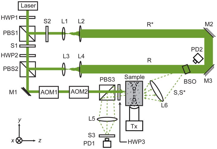
Light focusing plays a central role in biomedical imaging, manipulation, and therapy. In scattering media, direct light focusing becomes infeasible beyond one transport mean free path. All previous methods1-3 to overcome this diffusion limit lack a practical internal "guide star."4 Here we proposed and experimentally validated a novel concept, called Time-Reversed Ultrasonically Encoded (TRUE) optical focusing, to deliver light into any dynamically defined location inside a scattering medium. First, diffused coherent light is encoded by a focused ultrasonic wave to provide a virtual internal "guide star"; then, only the encoded light is time-reversed and transmitted back to the ultrasonic focus. The TRUE optical focus-defined by the ultrasonic wave-is unaffected by multiple scattering of light. Such focusing is especially desirable in biological tissue where ultrasonic scattering is ~1000 times weaker than optical scattering. Various fields including biomedical and colloidal optics can benefit from TRUE optical focusing.


Conflict of interest statement

Author Information X. X. and H. L. declare no competing financial interests. L. W. has a financial interest in Microphotoacoustics, Inc. and Endra, Inc., which, however, did not support this work. Readers are welcome to comment on the online version of this article at www.nature.com/nature.

Figures

Fig. 1
Fig. 1
Schematic of the experimental setup for TRUE optical focusing. HWPi, ith half-wave plate; PBSi, ith polarizing beam splitter; Si, ith shutter; Mi, ith mirror; AOMi, ith acousto-optic modulator; Li, ith lens; PDi, ith photodiode; R, reference beam; R*, conjugated reference beam; S, signal light; S*, time-reversed signal light; BSO, Bi12SiO20; Tx, ultrasonic transducer with centre frequency fa= 3.5 MHz, focal length = 38 mm, and focal width = 0.87 mm. Coordinates: x = sample scanning axis, y = acoustical axis, and z = optical axis. The time-reversal procedure consisted of recording and readout of a hologram. To record a hologram, S1 was opened, and S2 and S3 were closed for 190 ms; to read the hologram, S1 was closed, and S2 and S3 were opened for 10 ms.
Fig. 2
Fig. 2
2D Monte Carlo simulation of light propagation inside a scattering slab whose dimensions were x=160 L and z= 40 L . Initially, a broad (a–d) or a narrow (e–h) light beam was normally incident at the origin of the coordinates. In each panel, the top plot shows the trajectories while the bottom plot shows the photon density distribution(s) along the optical axis (total density shown in black). a & e, diffusive trajectories of S(fs) propagating through the slab: some (shown in green) reach the phase-conjugate mirror and the others (shown in blue) do not. b & f, trajectories of S* ( fs ) propagating back through the slab and converging to the incident point. c & g, trajectories of S( f ) (shown in blue) and the ultrasonically encoded component S(f+) (shown in green) inside the slab. d & h, trajectories of S*(f+) converging back to the ultrasonic focus (shown in green) then back to the incident point (shown in magenta). The black circles in the middle of the slab denote the ultrasonic focus. UE: Ultrasonically Encoded light.
Fig. 3
Fig. 3
Results from four imaging experiments validating TRUE optical focusing. a, photograph of the imaged sample dissected at the middle plane containing two absorbing objects (Obj1 and Obj2) and one scattering object (Obj3). The object dimensions were x = 1.3 mm, y = 4.5 mm, and z = 1 mm for the two absorbing objects and x = 1.7 mm, y = 4.5 mm, and z = 0.6 mm for the scattering object, while the full dimensions of the sample were x = y = 60 mm and z = 10 mm. b, comparison of the normalized DC, TRDC, and TRUE images of the sample. The absolute strengths of the TRDC and TRUE signals were ~3,000 mV and ~30 mV, respectively. The objects could not be distinguished in the DC and TRDC images, while in the TRUE image the objects were clearly shown against the background with 61% contrast for the absorbing objects and 31% contrast for the scattering object. c, comparison of the UOT and TRUE images of the sample to demonstrate the square law: the TRUE signal is proportional to the square of the UOT signal (UOT2). The FWHMs of the point-spread functions were 0.89 mm (UOT) and 0.63 mm (TRUE), whose ratio is 1.4 (≈ 2 ). In b and c, the symbols represent experimental data while the solid curves represent Gaussian fitting.

Similar articles

Cited by

References

    1. Vellekoop IM, Mosk AP. Focusing coherent light through opaque strongly scattering media. Opt Lett. 2007;32:2309–2311. - PubMed
    1. Vellekoop IM, van Putten EG, Lagendijk A, Mosk AP. Demixing light paths inside disordered metamaterials. Opt Exp. 2008;16:67–80. - PubMed
    1. Yaqoob Z, Psaltis D, Feld MS, Yang CH. Optical phase conjugation for turbidity suppression in biological samples. Nature Photon. 2008;2:110–115. - PMC - PubMed
    1. Primmerman CA, Murphy DV, Page DA, Zollars BG, Barclay HT. Compensation of Atmospheric Optical Distortion Using a Synthetic Beacon. Nature. 1991;353:141–143.
    1. Popoff SM, et al. Measuring the Transmission Matrix in Optics: An Approach to the Study and Control of Light Propagation in Disordered Media. Phys Rev Lett. 2010;104:100601–100604. - PubMed