Review
. 2011 May 2;11(5):10.1167/11.5.1 1.
doi: 10.1167/11.5.1.

Surface color perception and equivalent illumination models

Affiliations
Review

Surface color perception and equivalent illumination models

David H Brainard et al. J Vis. .

Abstract

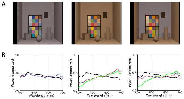
Vision provides information about the properties and identity of objects. The ease with which we perceive object properties belies the difficulty of the underlying information-processing task. In the case of object color, retinal information about object reflectance is confounded with information about the illumination as well as about the object's shape and pose. There is no obvious rule that allows transformation of the retinal image to a color representation that depends primarily on object surface reflectance. Under many circumstances, however, object color appearance is remarkably stable across scenes in which the object is viewed. Here, we review a line of experiments and theory that aim to understand how the visual system stabilizes object color appearance. Our emphasis is on models derived from explicit analysis of the computational problem of estimating the physical properties of illuminants and surfaces from the retinal image, and experiments that test these models. We argue that this approach has considerable promise for allowing generalization from simplified laboratory experiments to richer scenes that more closely approximate natural viewing. We discuss the relation between the work we review and other theoretical approaches available in the literature.


Figures

Figure 1
Figure 1. Image formation
Individual locations on a coffee mug can reflect very different spectra. The uniform patches at the top of the figure show image values from the locations indicated by the arrows. The mug itself, however, is readily perceived as homogeneous blue. After Figure 1 of Xiao & Brainard (2008).
Figure 2
Figure 2. Flat-matte-diffuse conditions
A collection of flat, matte surfaces is illuminated by a diffuse light source with spectral power distribution E(λ). The color signal Cj(λ) reflected from the jth surface is given by Cj(λ) = E(λ)Sj (λ), where Sj (&laambda;) is the surface reflectance function of that surface. The cone excitation vector elicited by Cj (λ) is ρj The set of ρj, across the retinal image, {ρ1,…,ρn}, is the information available to computational algorithms that seek to estimate illuminant and surface properties under flat-matte-diffuse conditions. It is also the information available to the human visual system for producing the perceptual representation that is color appearance. When we consider the properties (either physical or perceptual) of a specific surface (denoted the jth surface), we often refer to it as the test surface and refer to the collection of surfaces making up the rest of the scene together with the illuminant as the scene context.
Figure 3
Figure 3. Equivalent illumination models
The information available about the scene (the retinal image {ρ1,…, ρn}) is used to form an estimate ε̃ of the illuminant coordinates, the equivalent illuminant. This estimate in turn determines how the color signal reflected from each scene surface is transformed to the perceptual representation that is color appearance.
Figure 4
Figure 4. Equivalent illuminants in flat-matte scenes
A. Asymmetric matching data and predictions. Data are shown as the CIELAB a* and b* coordinates of the color signal reaching the eye from the reference and matching test surfaces. Open black circles plot the a*b* coordinates of the color signal reflected from a reference surface. Closed black circles are the asymmetric matches, plotted as the coordinates of the light reflected from matching test surfaces. Points indicated by closed green circles (and connected to open black circles by solid green lines) show where the matches would lie for a color constant visual system. Equivalent illumination model predictions for two hypothetical choices of equivalent illuminant are shown by closed red and closed blue circles, connected to black open circles by red and blue dashed lines respectively. The red closed circles are in fact the predictions of the best fitting equivalent illuminant. B) Reference illuminant spectrum (solid black line), test illuminant spectrum (solid green line) and two equivalent illuminant spectra (red and blue dashed lines). These correspond to the equivalent illuminant predictions shown in Panel A. The equivalent illuminant shown in red provides the best fit to the data. Spectra shown are all within the parametric model for illuminant spectra, and therefore differ from the physical spectra used in the experimental apparatus. C) Quality of equivalent illuminant predictions. The CIELAB a*, b* and L* components of the predictions are plotted against the corresponding components of the asymmetric matches. All conversions to CIELAB were done using the test illuminant’s tristimulus coordinates as the reference white.
Figure 5
Figure 5
A) Three scenes studied by Delahunt & Brainard (2004). Subjects viewed renderings of the scenes in stereo and set the chromaticity of a test patch (location is indicated by black rectangle) to appear achromatic. Measurements were made for 17 scenes. Across some scenes, only the illuminant changed (e.g., left to center). Across other scenes, both the illuminant and the reflectance of the back surface changed (e.g., left to right). This latter manipulation eliminated local contrast as a cue to the illuminant change. B) The measured achromatic locus may be interpreted as the visual system’s estimate of the illuminant (Brainard et al., 2006). This is shown as a red dashed line in all three panels. The corresponding illuminant estimated by the Bayesian algorithm is shown as a blue dashed line in each panel. In the left panel, the scene illuminant is shown as a solid black line. This line is replotted in the middle and right panels for comparison. In those panels, the physical illuminant is shown as a solid green line. The Bayesian algorithm predicts the human equivalent illuminants well, both for cases of good constancy (e.g., left to center panel scene change) and for cases of poor constancy (e.g., left to right panel scene change).
Figure 6
Figure 6. The effect of surface orientation
Photograph of the same flat-matte surface at two different slants relative to a directional light source. The figure illustrates that even when the configuration of light sources in a three-dimensional scene is held fixed, the three-dimensional pose of an object affects the amount of light reflected to the observer. Reprinted from Figure 1 of Ripamonti et al. (2004).
Figure 7
Figure 7. Matching functions
A. The normalized surface albedo of a surface of constant luminance is plotted versus surface azimuth for a scene illuminated by a combination of collimated and diffuse sources (solid green curve). We refer to such a curve as a matching function. Surface albedo is normalized so that its minimum is one. This minimum occurs when the surface azimuth is identical to the azimuth of the collimated source. When the surface azimuth differs from that of the punctuate source, the surface must have higher albedo to produce the same luminance. If a visual system misestimates the azimuth of the collimated light source, but otherwise computes an estimate of surface albedo correctly, the resulting plot of estimated normalized surface albedo vs. azimuth will be shifted so that its minimum falls at the estimated azimuth but is otherwise unchanged. Two examples are shown as dashed red and blue lines. B. If a visual system misestimates the relative intensity of the collimated source but otherwise computes an estimate of surface albedo correctly, the resulting plot of relative surface albedo vs. azimuth will be shallower or steeper as shown but otherwise unchanged. Two examples are shown as dashed red and blue lines. The solid green curve is replotted from Panel A.
Figure 8
Figure 8. Estimates of equivalent illuminants in three-dimensional scenes
A. Data and fit for one observer redrawn from Boyaci et al (2003). Observers viewed rendered scenes illuminated by a combination of collimated and diffuse light sources and matched the perceived albedo of a reference surface to a test surface within the scene that varied in orientation. The luminance rather than the albedo of the test surface was held constant across orientations. Viewing was binocular. The true azimuth of the punctuate source is marked by a green vertical line and the true matching function is shown as a solid green curve. The observer’s fitted matching function has an azimuth estimate close to the true value but is shallower. The equivalent illuminant has a higher diffuseness value than the true. The fit matching function (dashed red curve) is in good agreement with the data. In particular, the observer is sensitive to the effect of surface azimuth on the color signal in scenes illuminated by a combination of punctuate and diffuse sources. B,C. Data for one observer in two conditions redrawn from Ripamonti et al. (2004). Observers viewed real scenes illuminated by a combination of collimated and diffuse light sources and matched the perceived albedo of a reference surface to a test surface within the scene that varied in orientation. Viewing was binocular. In this experiment, the luminance of the test surface was not held constant across orientations, but measurements were made for a number of different surface albedos. The data here are combined across surface albedos and replotted to show the effect inferred for constant luminance. Each panel shows a different illuminant configuration. The two configurations differed primarily in the azimuth of the collimated source. The format is as in Panel A. Once again, the observer’s settings are consistent with an equivalent illuminant whose azimuth parameter is close to that of the actual collimated source but whose diffuseness is higher than that of the physical illuminant.

Similar articles

Cited by

References

    1. Arend LE, Reeves A. Simultaneous color constancy. Journal of the Optical Society of America A. 1986;3:1743–1751. - PubMed
    1. Barlow HB. Possible principles underlying the transformations of sensory messages. In: Rosenblith WA, editor. Sensory communication. M.I.T. Press and John Wiley & Sons, Inc; 1961. pp. 217–234.
    1. Beck J. Judgments of surface illumination and lightness. Journal of Experimental Psychology. 1961;61:368–373. - PubMed
    1. Beck J. Surface Color Perception. Ithaca: Cornell University Press; 1972.
    1. Bell DE, Raiffa H, Tversky A. Decision Making: Descriptive, Normative, and Prescriptive Interactions. Cambridge: Cambridge University Press; 1988.

Publication types