. 2011 Jul;4(4):415-24.
doi: 10.1161/CIRCIMAGING.111.963868. Epub 2011 May 2.

X-ray magnetic resonance fusion to internal markers and utility in congenital heart disease catheterization

Affiliations

X-ray magnetic resonance fusion to internal markers and utility in congenital heart disease catheterization

Yoav Dori et al. Circ Cardiovasc Imaging. 2011 Jul.

Abstract

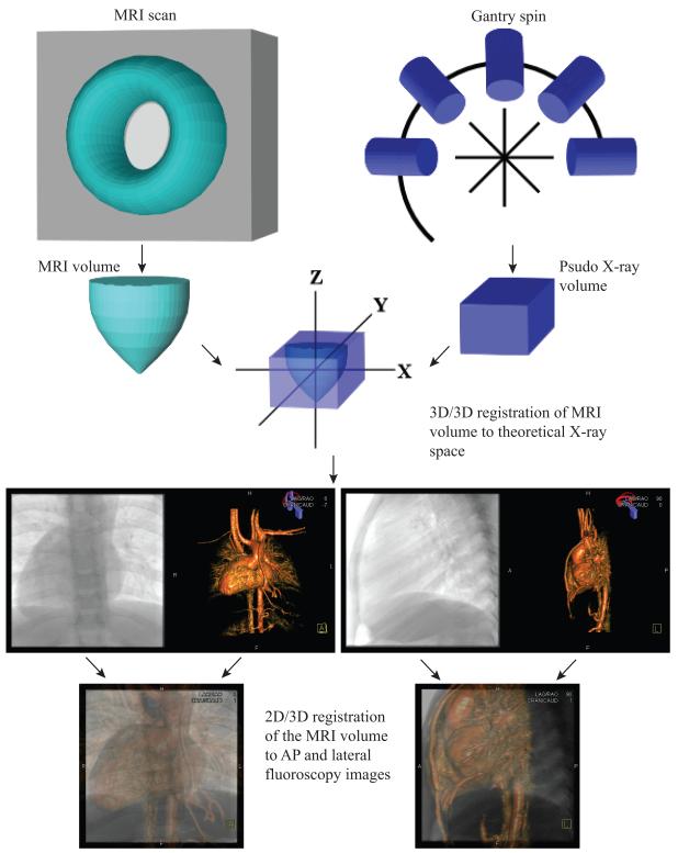
Background: X-ray magnetic resonance fusion (XMRF) allows for use of 3D data during cardiac catheterization. However, to date, technical requirements have limited the use of this modality in clinical practice. We report on a new internal-marker XMRF method that we have developed and describe how we used XMRF during cardiac catheterization in congenital heart disease.

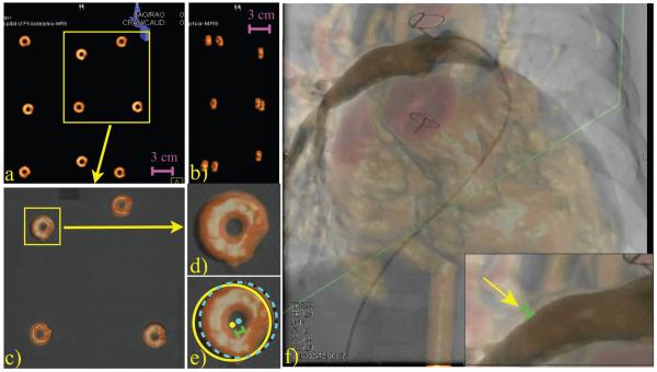
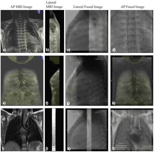
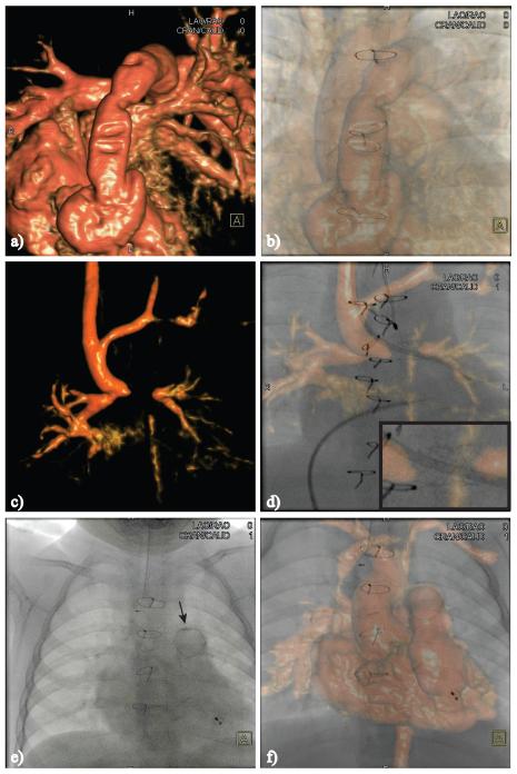
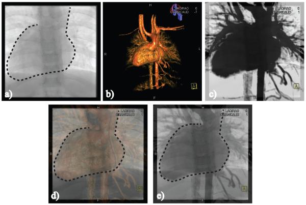
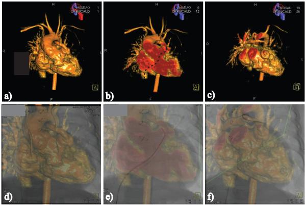
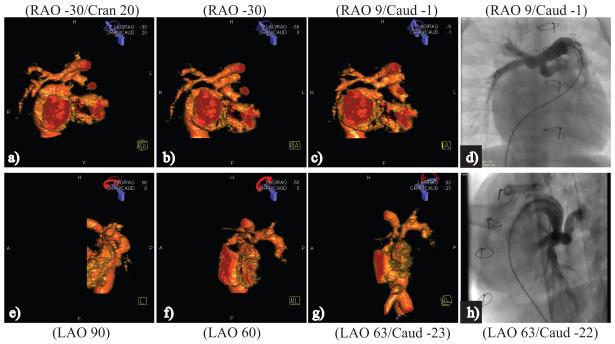
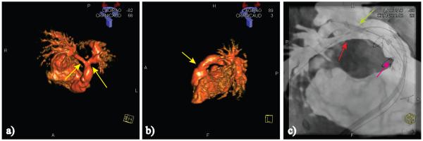
Methods and results: XMRF was performed in a phantom and in 23 patients presenting for cardiac catheterization who also needed cardiac MRI for clinical reasons. The registration process was performed in < 5 minutes per patient, with minimal radiation (0.004 to 0.024 mSv) and without contrast. Registration error was calculated in a phantom and in 8 patients using the maximum distance between angiographic and 3D model boundaries. In the phantom, the measured error in the anteroposterior projection had a mean of 1.15 mm (standard deviation, 0.73). The measured error in patients had a median of 2.15 mm (interquartile range, 1.65 to 2.56 mm). Internal markers included bones, airway, image artifact, calcifications, and the heart and vessel borders. The MRI data were used for road mapping in 17 of 23 (74%) cases and camera angle selection in 11 of 23 (48%) cases.

Conclusions: Internal marker-based registration can be performed quickly, with minimal radiation, without the need for contrast, and with clinically acceptable accuracy using commercially available software. We have also demonstrated several potential uses for XMRF in routine clinical practice. This modality has the potential to reduce radiation exposure and improve catheterization outcomes.


Figures

Figure 1
Figure 1
XMRF registration protocol. Images at the bottom of the figure show the result of the registration process as seen with the AP camera in the AP (bottom left) projection and with the AP camera rotated to the lateral projection (bottom right).
Figure 2
Figure 2
Method used for error calculation. A and B, Volume-rendered MRI image of the phantom in the AP and lateral projections. C, AP projection of 4 dual-modality markers enclosed by the box in A fused to the x-ray image. D, Magnified view of overlaid marker is seen. E, The same marker is seen with a light blue dashed line surrounding the marker as seen on the MRI image and a yellow solid line surrounding the same marker as seen on the x-ray image. The error was calculated as the distance between the center of the 2 circular regions (light green bar). F, Contrast injection into the proximal right pulmonary artery (RPA) with insert showing a magnified view of the RPA. Yellow arrow points to the location where the error was measured; the green bar indicates the magnitude of the error at this location.
Figure 3
Figure 3
Shows XMRF to the spinal cord (A through D), sternum (E through H), and the airway (I through L).
Figure 4
Figure 4
A and B, XMRF to imaging artifact from sternal wires that resulted in indents on an RV-PA conduit. C and D, Susceptibility artifact from a stent produced a gap in the MRI image of the left pulmonary artery in a patient with a Glenn shunt. D, Insert shows a close-up view of the stent registered between the 2 PA stumps. E and F, Registration to distal conduit calcification. Arrow in E points toward a ring of calcification that formed at the distal end of a RV-PA conduit. All images are in the AP projection.
Figure 5
Figure 5
A, Dashed line traces the heart border and the left lateral border of the aorta on the x-ray image. B, XMRF to heart and vessel borders using volume-rendered MRI image; C, maximal intensity projection–rendered image showing the largest cross-section of the heart and great vessels. D through E, Registered volume-rendered MRI and maximal intensity projection images. All images are in the AP projection.
Figure 6
Figure 6
A through C, Images of a patient with a small RV-PA conduit that were stored as a collection of bookmarks for roadmapping; D through F, the same images during the catheterization process. B, Pathway from the inferior vena cava to the entrance to the conduit is shown (dashed arrow) on an image that was created with an AP cut-plane. E, Corresponding catheter course is shown. C, Roadmap image that was created with an oblique cut-plane exposing the PA confluence and a hypoplastic left pulmonary artery (LPA). F, Corresponding catheter course with the tip of the catheter positioned in the distal LPA.
Figure 7
Figure 7
Camera angle selection in a patient with complex PA anatomy. In this case, the left pulmonary artery (LPA) originated from the proximal right pulmonary artery and immediately took a 90° turn to the left. There was also proximal LPA hypoplasia. A through D correspond to the AP camera and E through H to the lateral camera. The anatomy is shown in the conventional camera angles (A and B, E and F) and in the angle that was chosen for the contrast angiogram (C and G). D and H, Corresponding contrast angiograms.
Figure 8
Figure 8
Anatomy of a patient with an RV-PA conduit and bilateral proximal branch pulmonary artery stenosis (yellow arrows). A and B, Volume-rendered MRI images show the 3 stenotic regions. C, Image taken after a Palmaz XL 40×10-mm stent (Cordis) was placed using an 18×3.5 BiB (NuMed Inc) balloon in the proximal conduit (cyan arrow); a Genesis 3910B stent (Cordis) was placed with a 10×3.5 BiB in the proximal right pulmonary artery (RPA) (red arrow), and, simultaneously, a Genesis 2910B stent was placed using a 12×3 BiB in the proximal left pulmonary artery (light green arrow). C, Example of a nonperiodic error caused by distortion of the distal RPA by a stiff wire, resulting in the wire appearing to be outside of the vessel (light blue arrow).

Comment in

References

    1. Saikus CE, Lederman RJ. Interventional cardiovascular magnetic resonance imaging: a new opportunity for image-guided interventions. J Am Coll Cardiol Cardiovasc Imaging. 2009;2:1321–1331. - PMC - PubMed
    1. Knecht S, Skali H, O’Neill MD, Wright M, Matsuo S, Chaudhry GM, Haffajee CI, Nault I, Gijsbers GH, Sacher F, Laurent F, Montaudon M, Corneloup O, Hocini M, Haissaguerre M, Orlov MV, Jais P. Computed tomography-fluoroscopy overlay evaluation during catheter ablation of left atrial arrhythmia. Europace. 2008;10:931–938. - PubMed
    1. Sra J, Krum D, Malloy A, Vass M, Belanger B, Soubelet E, Vaillant R, Akhtar M. Registration of three-dimensional left atrial computed tomographic images with projection images obtained using fluoroscopy. Circulation. 2005;112:3763–3768. - PubMed
    1. Sra J, Narayan G, Krum D, Akhtar M. Registration of 3d computed tomographic images with interventional systems: implications for catheter ablation of atrial fibrillation. J Interv Card Electrophysiol. 2006;16:141–148. - PubMed
    1. Sra J, Narayan G, Krum D, Malloy A, Cooley R, Bhatia A, Dhala A, Blanck Z, Nangia V, Akhtar M. Computed tomography-fluoroscopy image integration-guided catheter ablation of atrial fibrillation. J Cardiovasc Electrophysiol. 2007;18:409–414. - PubMed