

Feasibility of Neural Stimulation With Floating-Light-Activated Microelectrical Stimulators
- PMID: 21552457
- PMCID: PMC3087211
- DOI: 10.1109/TBCAS.2011.2114882
Feasibility of Neural Stimulation With Floating-Light-Activated Microelectrical Stimulators
Abstract
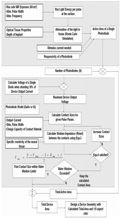
Neural microstimulation is becoming a powerful tool for the restoration of impaired functions in the central nervous system. Microelectrode arrays with fine wire interconnects have traditionally been used in the development of these neural prosthetic devices. However, these interconnects are usually the most vulnerable part of the neuroprosthetic implant that can eventually cause the device to fail. In this paper, we investigate the feasibility of floating-light-activated microelectrical stimulators (FLAMES) for wireless neural stimulation. A computer model was developed to simulate the micro stimulators for typical requirements of neural activation in the human white and gray matters. First, the photon densities due to a circular laser beam were simulated in the neural tissue at near-infrared (NIR) wavelengths. Temperature elevation in the tissue was calculated and the laser power was retrospectively adjusted to 325 and 250 mW/cm(2) in the gray and white matters, respectively, to limit ΔT to 0.5 °C. Total device area of the FLAMES increased with all parameters considered but decreased with the output voltage. We conclude that the number of series photodiodes in the device can be used as a free parameter to minimize the device size. The results suggest that floating, optically activated stimulators are feasible at submillimeter sizes for the activation of the brain cortex or the spinal cord.
Figures


References
-
- Schmidt EM, Bak MJ, Hambrecht FT, Kufta CV, O’Rourke DK, Vallabhanath P. Feasibility of a visual prosthesis for the blind based on intracortical microstimulation of the visual cortex. Brain. 1996;119:507–522. - PubMed
-
- Saigal R, Renzi C, Mushahwar VK. Intraspinal microstimulation generates functional movements after spinal-cord injury. IEEE Trans. Neural Syst. Rehab. Eng. 2004 Dec.12(4):430–440. - PubMed
-
- Mushahwar VK, Gillard DM, Gauthier MJA, Prochazka A. Intraspinal microstimulation generates locomotor-like and feedback-controlled movements. IEEE Trans. Neural Syst. Rehab. Eng. 2002 Mar.10(1):68–81. - PubMed
-
- Tai C, Booth AM, Robinson CJ, De Groat WC, Roppolo JR. Multi-joint movement of the cat hindlimb evoked by microstimulation of the lumbosacral spinal cord. Exper. Neurol. 2003;183:620–627. - PubMed
-
- Otto KJ, Rousche PJ, Kipke DR. Microstimulation in auditory cortex provides a substrate for detailed behaviors. Hear. Res. 2005;210:112–117. - PubMed
Grants and funding
LinkOut - more resources
Full Text Sources
Other Literature Sources
Miscellaneous
