. 2006 Jan;2(1):e19.
doi: 10.2349/biij.2.1.e19. Epub 2006 Jan 1.

Intensity modulated radiotherapy: advantages, limitations and future developments

Affiliations

Intensity modulated radiotherapy: advantages, limitations and future developments

Ky Cheung. Biomed Imaging Interv J. 2006 Jan.

Abstract

Intensity modulated radiotherapy (IMRT) is widely used in clinical applications in developed countries, for the treatment of malignant and non-malignant diseases. This technique uses multiple radiation beams of non-uniform intensities. The beams are modulated to the required intensity maps for delivering highly conformal doses of radiation to the treatment targets, while sparing the adjacent normal tissue structures. This treatment technique has superior dosimetric advantages over 2-dimensional (2D) and conventional 3-dimensional conformal radiotherapy (3DCRT) treatments. It can potentially benefit the patient in three ways. First, by improving conformity with target dose it can reduce the probability of in-field recurrence. Second, by reducing irradiation of normal tissue it can minimise the degree of morbidity associated with treatment. Third, by facilitating escalation of dose it can improve local control. Early clinical results are promising, particularly in the treatment of nasopharyngeal carcinoma (NPC). However, as the IMRT is a sophisticated treatment involving high conformity and high precision, it has specific requirements. Therefore, tight tolerance levels for random and systematic errors, compared with conventional 2D and 3D treatments, must be applied in all treatment and pre-treatment procedures. For this reason, a large-scale routine clinical implementation of the treatment modality demands major resources and, in some cases, is impractical. This paper will provide an overview of the potential advantages of the IMRT, methods of treatment delivery, and equipment currently available for facilitating the treatment modality. It will also discuss the limitations of the equipment and the ongoing development work to improve the efficiency of the equipment and the treatment techniques and procedures.

Keywords: IGRT; IMRT; dose optimisation; motion compensation.


Figures

Figure 1
Figure 1
A dosimetry comparison between (a) a 3-beam conventional 2D treatment, (b) a 6-beam conventional 3D conformal RT treatment, and (c) a 7-beam IMRT treatment. The PTV is represented by the solid red line. The 100% and 70% of the prescription dose are shown by the green and red colour-washed areas. A better dose conformity to the PTV can be achieved in the IMRT treatment.
Figure 2
Figure 2
Fluence intensity map created by a pair of MLC leaf pair sliding across the radiation field.
Figure 3
Figure 3
Typical pattern of movement of the MLC leaf pairs when operating in the dynamic MLC mode (available for download from http://www.biij.org/2006/1/e19).
Figure 4
Figure 4
The dose distribution of an IMSRT treatment of a chondroma. A higher dose (shown in red colour-washed area) can simultaneously be delivered to the main bulk of the lesion while the rest of the PTV is given the normal dose (shown in green colour-washed area). This is a simple form of dose painting or sculpting.
Figure 5
Figure 5
Inter-fraction treatment set up errors (shift in isocentre) in the lateral direction of IMRT treatments (represented by the yellow histogram) and stereotactic treatments (represented by the blue histogram). Similar results are find in the superior-inferior and the anteria-posteria directions. The data confirm that stereotactic set up can reduce the amount of inter-fractional geometrical errors.
Figure 6
Figure 6
Principle of conventional forward planning. The planner starts with a set of beam weights and profiles to obtain a plan by trial-and-error process.
Figure 7
Figure 7
Principle of inverse planning- The planner define the required dose & dose distribution for treatment and the computer can calculate and optimised the beam intensity patterns of the individual IMRT beams to meet the dose requirements.
Figure 8
Figure 8
A thermal plaster patient immobilisation cast used in IMRT treatment.
Figure 9
Figure 9
Stability of thermal plaster cast immobilisation system for NPC treatment. The diagrams show the frequency distribution of inter-fraction treatment positioning errors due to isocentre shift in the (a) lateral direction, (b) anterior-posterior direction and (c) superior-inferior direction. Frequency distribution of for patient immobilisation in IMRT treatment.
Figure 10
Figure 10
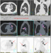
A PET-CT image can provide more accurate diagnostic and staging information on a lung tumour for IMRT treatment planning (courtesy of Dr. Hector Ma, St. Teresa's Hospital, Hong Kong)
Figure 11
Figure 11
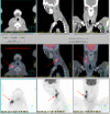
The fusion of CT and PET provide more accurate information for IMRT treatment planning. In this example, the spread of lymph mode metastasis of a nasopharyngeal carcinoma is can be clearly identified (courtesy of Dr. Hector Ma, St. Teresa's Hospital, Hong Kong)
Figure 12
Figure 12
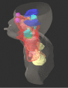
Some of the critical normal organs of interest in NPC treatment. The PTV is contoured in red.
Figure 13
Figure 13
A linear accelerator with built-in kV cone beam CT system for IGRT treatment delivery (courtesy of Varian Medical Systems)
Figure 14
Figure 14
CT images produced by the cone beam CT system of a linear accelerator (courtesy of Professor Lei Xing, Stanford University School of Medicine, USA)
Figure 15
Figure 15
A tomotherapy unit (courtesy of Hong Kong Sanatorium & Hospital, Hong Kong)
Figure 16
Figure 16
On-line treatment verification by matching of the planning CT image (bottom left) with the tomotherapy treatment set up image (top left) immediately before treatment delivery without moving the patient (courtesy of Hong Kong Sanatorium & Hospital)
Figure 17
Figure 17
Video clip on a lung tumour movement during a respiratory cycle (available for download from http://www.biij.org/2006/1/e19).
Figure 18
Figure 18
Gating of radiotherapy treatment beams by respiratory motion waveform to compensate for target movement.
Figure 19
Figure 19
Video clip on principle of the BrainLab Exac-Tract X-ray treatment (courtesy of BrainLab, Germany) (available for download from http://www.biij.org/2006/1/e19).

References

    1. Curran BH. Sternick ES. The Theory & Practice of Intensity Modulated Radiation Therapy. Advanced Medical Publishing; 1997. Conformal therapy using a multileaf intensity modulating collimator; pp. 75–90.
    1. Bortfeld TR, Kahler DL, Waldron TJ, et al. X-ray field compensation with multileaf collimators. Int J Radiat Oncol Biol Phys. 1994;28(3):723–30. - PubMed
    1. Spirou SV, Chui CS. Generation of arbitrary intensity profiles by dynamic jaws or multileaf collimators. Med Phys. 1994;21(7):1031–41. - PubMed
    1. Yu CX. Intensity-modulated arc therapy with dynamic multileaf collimation: an alternative to tomotherapy. Phys Med Biol. 1995;40(9):1435–49. - PubMed
    1. Adler JR, Cox RS. Preliminary clinical experience with the Cyberknife: Image-guided Stereotactic radiosurgery. Radiosurgery. 1995;1:316–26.

LinkOut - more resources